
A NonLinear Educating Company
Turning a Vintage Toy Piano into a MIDI Controller Using Arduino
Liam Lacey on Jul 31, 2015 in DIY & Hacking | 25 comments
In May 2015 I attended MIDI Hack—a 24-hour hackathon that ‘celebrates the protocols and technologies that are the backbone of analog and digital music creation’, held at the Ableton HQ in Berlin. A 24-hour hackathon is an event where a group of developers, designers and artists come together for 24 hours to create a piece of software or hardware, either individually or within teams, often with a chance to win prizes at the end. For my hack I decided to convert a vintage wooden toy piano into a polyphonic, velocity-sensitive MIDI controller using the Arduino microcontroller platform; a hack that I ended up winning a prize for. It was a fairly simple project for getting started with the Arduino platform, so I thought I’d create a tutorial on the creation process for those of you who are interested in learning the Arduino platform, especially in regard to MIDI and audio.
If you read a previous article of mine, you would know that I highly recommend the Arduino platform for making DIY MIDI controllers. I chose Arduino for this project over the other suggested platforms as it provides you with a lot of control over what you do with the input/output data, however it is still extremely beginner friendly with a lot of official support and guides. This guide is aimed at individuals who are complete beginners at electronics, software development, and Arduino.
Here is a list of things you will need for this project. All electronic components mentioned here can be bought from any good DIY/hobbyist electronics store, such as SparkFun.
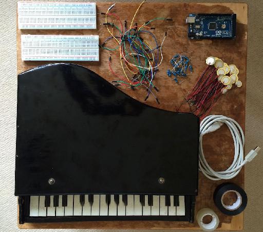
What You Will Need for this Project
- An acoustic wooden toy piano. I purchased my toy piano off of eBay for around $15, where there are usually a few available, however you can also occasionally find them in charity shops and flea markets. This project is based around pianos with a mechanism whereby the keys cause a hammer to strike some kind of resonating object; using a toy electronic keyboard will not work here.
- Arduino board. This is the microcontroller that will be ‘brain’ of the controller. The specific model of Arduino you will need here depends on the number of keys your piano has—if it has no more than six keys you can use an Arduino Uno, however you will most likely have more keys, which will require an Arduino Mega 2560. This relates to the number of analog inputs that each board has, and you’ll need one analog input for each key.
- Piezo Elements. Piezo element sensors are used for detecting vibration and knocks, and are popular components to use particularly in DIY and commercial drum trigger products. We will use these to detect presses from the keys, and you will need one of these for each key. You will need to consider the size of the piezos you require based on the size of the hammer heads within the piano—for my piano I needed piezos no bigger than 15mm. Also make sure the piezos are uncased and already have wires soldered to them.
- 1M ohm resistors. Resistors are the most basic and common component in electrical circuits, and are used to resist the flow of electricity. You will need one of these for each key/piezo.
- Wires. Arduino and breadboard-friendly wires, also known as male-to-male jumper wires, will be the easiest to use, and we will use these to connect all the components to the Arduino. You will need 2 for each key/piezo, as well as handful of extras.
- Solder-less breadboards. Solder-less breadboards allow you to create electronic circuits without the need to solder everything together. You may need a couple of these depending on how many keys your toy piano has.
- USB cable – to connect your Arduino to your computer.
- Double-sided sticky tape – to fix the piezo sensors, breadboards, and Arduino to the piano. You may also find it useful to have some regular or electrical tape for sticking down wires that could get in the way of piano hammers.
- The Arduino software. The Arduino software is used to program the Arduino board to do what we want it to do. This is freely available on the Arduino Software page and can be run on OS X, Windows, and Linux. You will also need to download the Arduino MIDI Library.
- Serial-to-MIDI and virtual MIDI port software. You will need some serial-to-MIDI software to convert the messages coming out of the Arduino into MIDI messages. I recommend the free Hairless MIDI to Serial Bridge application, however there are a number of others available. You will also need to use a virtual MIDI port to connect the output of Hairless to the input of your DAW or MIDI instrument. For this I recommend loopMIDI on Windows, or on OS X you can use its built-in IAC Driver. Alternatively, it is possible to ‘hack’ your Arduino Uno/Mega board so that it directly outputs MIDI messages, resulting in you not needing either of these pieces of software. This is quite advanced for an introductory Arduino project, but if you want to make the leap check out the HIDUINO project to see how this can be done.
- MIDI software. You’re building a USB-MIDI controller, so the only way to hear it make some sound is to connect it to a DAW or soft synth.
Step 1—Prepare your Piano
Before you can start inserting the electronics into your piano, you will need to remove the sound rods, or modify them so that you can mount the piezos to them. The set of rods in my piano were screwed to the underside of the top, so I simply unscrewed them to remove them, and then screwed in a block of wood that I could fasten the piezo sensors to. An alternative option would be to fix a thin flat piece of material (e.g., cardboard, wood) to the underside of the rods that the piezos can be fixed to, however you may find it more difficult to attach something to the rods, plus you may also find the rods will get in the way when attempting to insert the electronics.
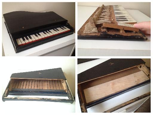
From top-left clockwise – The complete toy piano; The key and hammer mechanism; The metal sound rods inside the piano; The sound rods replaced with a block of wood for the piezo sensors to be fixed to.
Another modification you may need to do to your piano is adding a spike/point to the surface of the hammer that will strike the piezos. If the hammer heads are wider than the inner circle of the piezos they may not trigger the sensors properly, so to overcome this issue with my piano I taped small balls of solder onto the hammers to create a raised point.
Step 2—Attach the Piezos
We will now place the piezo sensors to the underside of the top of the piano where the hammer mechanisms would usually strike the sound rods when the keys are pressed. If your piano is handmade like mine, you will probably find that the hammers aren’t always straight and evenly spaced, making it a bit of a challenge to line up the piezos correctly. I found the best way to determine the position of the sensors was to turn the piano upside down so that the hammers are resting in their ‘pressed’ position, and marking with a pencil where each hammer is resting.
Once you’ve marked out the position of each hammer, place a strip of double-sided sticky tape over the markings, and stick each piezo in position. Try and make sure that none of the piezos are overlapping or touching, as this could cause a hammer to trigger multiple sensors. Also make sure that the side of the piezos where the wires are connected are closest to the back of the piano and away from where the hammers strike; you don’t want the hammer striking this part as it may prevent it from triggering the sensor properly. Also you need the wires facing the back of the piano, as this is where the Arduino and breadboards will go.
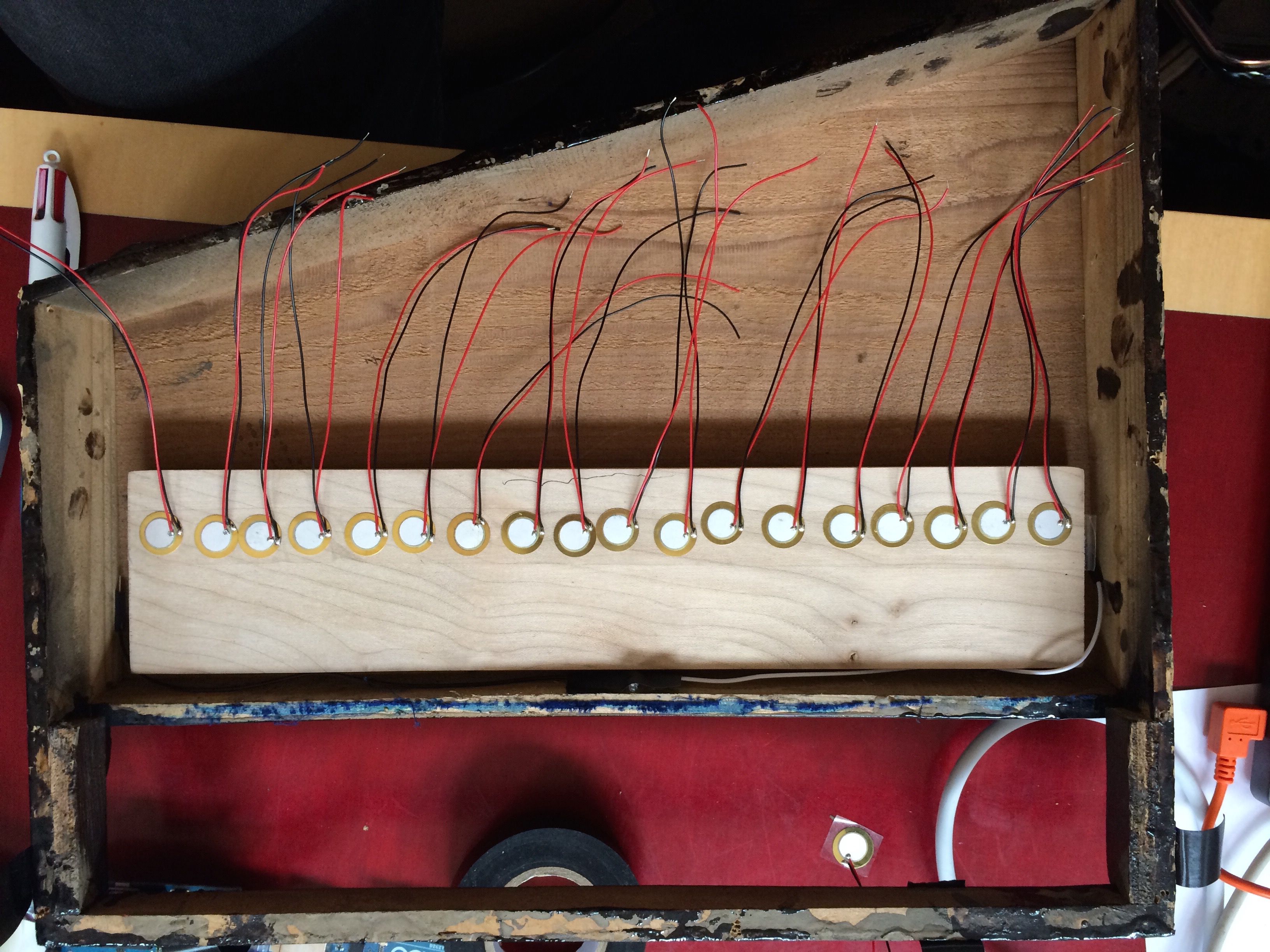
The attached piezo sensors
Step 3—Complete the Circuitry
In order to complete the circuitry you first need to attach the breadboard/s and Arduino board to the inside of the piano. If your piano opens from the bottom like mine did you will probably need to stick the boards to the underside of the top, however if the piano opens from the top you could probably complete the project by just placing the boards in bottom without needing to stick them down. Place the breadboard/s closest to the piezos, with the Arduino on the other side.
Next you need to attach the components to the breadboard/s. There are two main sections to most breadboards (as shown within the following diagram)—the four long horizontal strips of holes down the sides accompanied with red and blue/black lines, and the middle section with many smaller vertical strips of lines separated with a divider down the middle. Each of the four horizontal rows are separate ‘bus strips’, and offer a template for you to supply voltage (red line) and for you to ground (blue/black line) your circuits, whereas each of the smaller vertical ‘terminal strips’ each side of the divider are individual columns where you will connect most of your components.
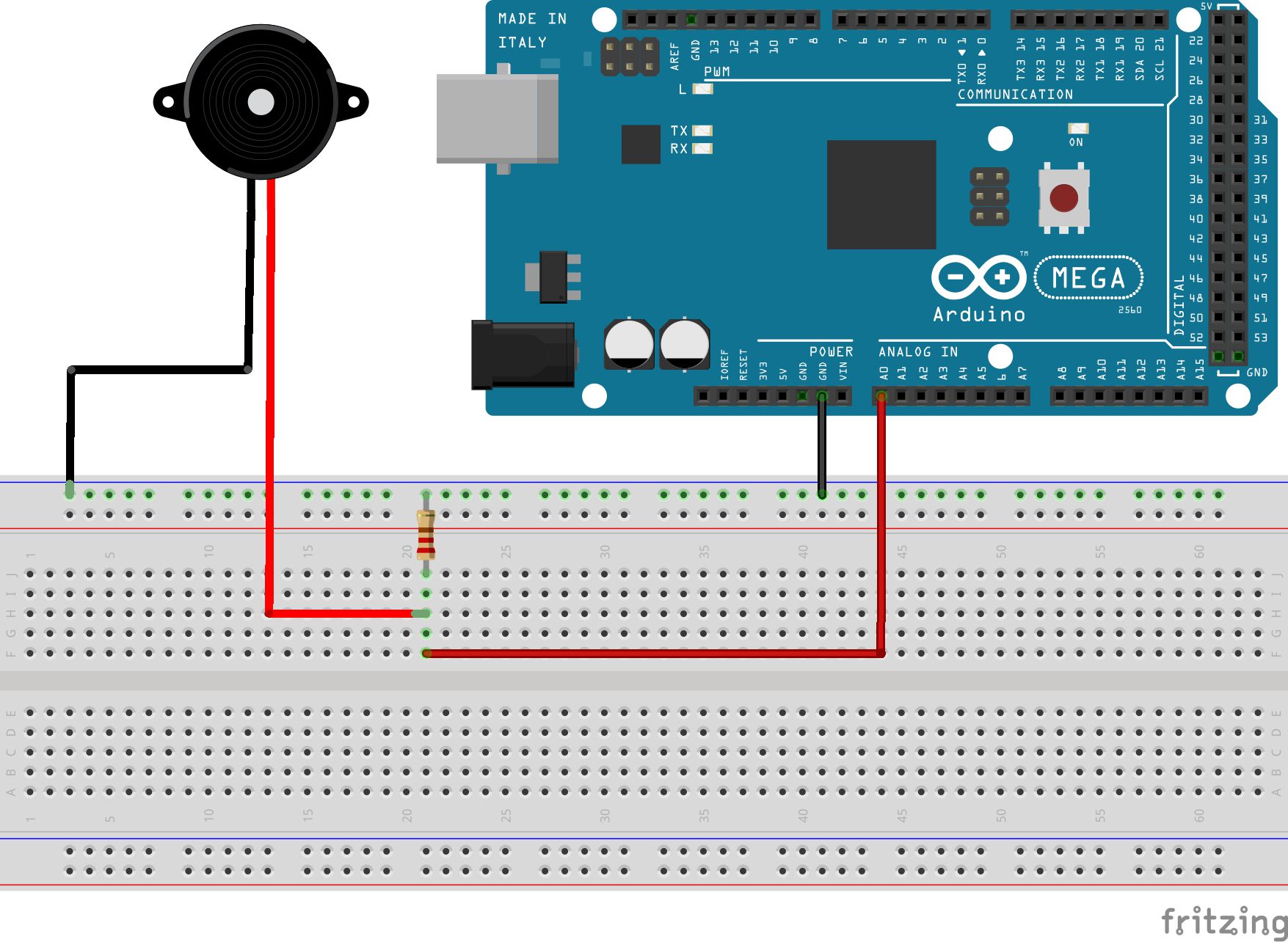
How to connect a single piezo sensor to an Arduino board
As displayed in the previous diagram, for each piezo/key, the black (ground) wire from the piezo needs to be connected to one of the ground bus strips, whereas the red (signal) wire needs to be connected to one of the terminal strips. You then need to connect a resistor (in any orientation) from the terminal strip to the ground strip; a wire from the terminal strip to one of the analog input pins on the Arduino, and another wire from the ground strip to one of the ground pins. You then need to repeat this circuit for each piezo, using a different terminal strip and Arduino analog input pin each time, as demonstrated in the following diagram.
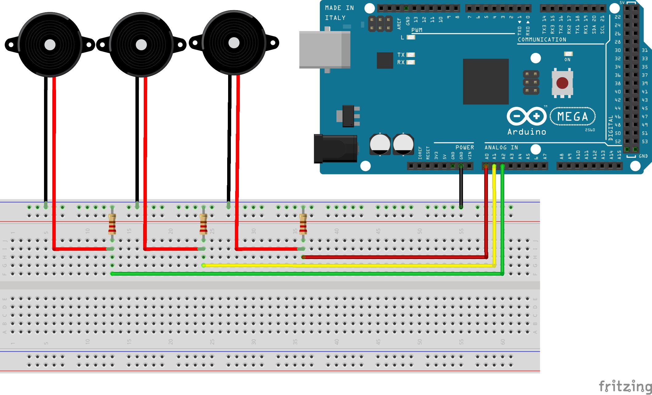
How to connect multiple piezo sensors to an Arduino board
I recommend using different color wires for each analog input connection, as this makes it easier to see what’s connected to what when trying to solve problems later on.
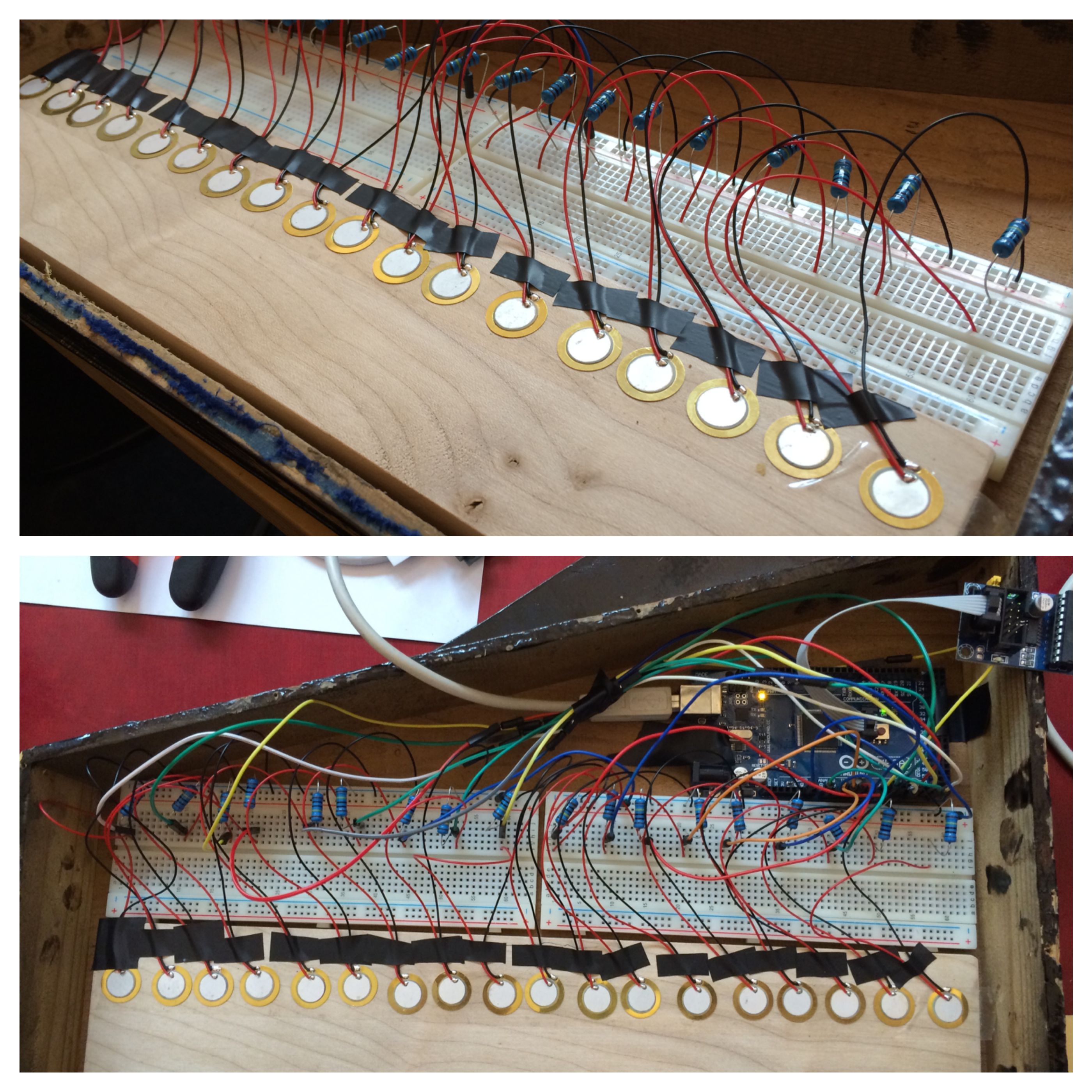
Top – Piezos and resistors attached to the breadboards. Bottom – The final electronics inside the piano.
Step 4—Edit and Upload the Code
After the hardware and the electronics are complete, you then need to upload some software to the Arduino board that will turn readings from the piezos into MIDI notes. Once you have downloaded and installed both the Arduino software and the Arduino MIDI Library, open the Arduino application and copy the below code into the Arduino text editor:
/*
MIDI Toy Piano Hack Code
*/

#include <MIDI.h>
MIDI_CREATE_DEFAULT_INSTANCE();

//========================================================================================
//Values you may need to change

//Set this value to the number of keys/piezos you are using
const int NUM_OF_KEYS = 16;
//Adjust this value to change the sensitivity of the piezos
const int THRESHOLD = 5;
//Set this value to the number of microseconds you want each MIDI note to last for
const int NOTE_LENGTH = 50;
//Adjust this value to set the range of MIDI note velocity values
const int VEL_SENSE_VAL = 2;

//Change this number to set what MIDI channel the MIDI notes are set to
const int midiChan = 1;
//Change these numbers to set what MIDI note number each key/piezo will send.
//Also make sure that the total number of numbers here matches the value of NUM_OF_KEYS
const int midiNote[NUM_OF_KEYS] = {86, 84, 83, 81, 79, 77, 76, 74, 72, 71, 69, 67, 65, 64, 62, 60};

//Change these values to set which analog input pins you are using
//Also make sure that the total number of values here matches the value of NUM_OF_KEYS
const int triggerSensor[NUM_OF_KEYS] = {A0, A1, A2, A3, A4, A5, A6, A7, A8, A9, A10, A11, A12, A13, A14, A15};

//=======================================================================================

//Variables for storing certain values
int triggerVal[NUM_OF_KEYS] = {0};
bool noteIsOn[NUM_OF_KEYS] = {false};
int midiNoteTime[NUM_OF_KEYS] = {0};
int midiVelocityVal[NUM_OF_KEYS] = {0};

void setup()
{
    MIDI.begin(MIDI_CHANNEL_OMNI);
    Serial.begin(115200); //REMOVE THIS LINE IF USING HIDUINO INSTEAD OF HAIRLESS
}

void loop()
{
    //repeat the below code for each anaolog input/piezo sensor
    for (int count; count < NUM_OF_KEYS; count++)
    {
        //read the piezo value
        triggerVal[count] = analogRead(triggerSensor[count]);

        //if the value is over the threshold and there isn't currently a note on for this piezo
        if (triggerVal[count] > THRESHOLD && noteIsOn[count] == false)
        {
            //get a velocity value based on the value
            midiVelocityVal[count] = triggerVal[count] * (127.0/1023.0);

            //increase sensitivity
            midiVelocityVal[count] *= VEL_SENSE_VAL;

            //make sure we don't go out of range
            if (midiVelocityVal[count] > 127)
            midiVelocityVal[count] = 127;

            //send a MIDI note-on message
            MIDI.sendNoteOn (midiNote[count], midiVelocityVal[count], midiChan);

            //flag that the note is on
            noteIsOn[count] = true;

            //start a timer for the note to be on for
            midiNoteTime[count] = NOTE_LENGTH;
        }

        //if the note is currently on
        if (noteIsOn[count] == true)
        {
            //reduce the time value by 1
            midiNoteTime[count]--;

            //if time value equals 0
            if (midiNoteTime[count] == 0)
            {
                //turn off the note
                MIDI.sendNoteOff (midiNote[count], 0, midiChan);
                noteIsOn[count] = false;
            }

        }

    }

    //pause the loop
    delay(1);
}
Teaching you how to use the Arduino software and how to code is a bit beyond the scope of this article, so I’ve placed many comments (lines beginning with ‘//’) in the code to describe what each part is doing. However there are a number of parts/values you may need to adjust to get it working with your piano, as well as options for setting the MIDI note values that the piano will transmit. You will find these at the top of the code:
- NUM_OF_KEYS – Set this value to match the number of keys/piezos you are using.
- THRESHOLD – This value determines how hard the hammers need to hit the piezos to trigger notes. A smaller value means you don’t have to press as hard, however if it’s too sensitive you may find hammers causes neighboring piezos to trigger as well.
- NOTE_LENGTH – This value sets how long (in microseconds) each MIDI note is played for.
- VEL_SENSE_VAL – This value is used in an equation to determine the MIDI velocity value of each note. A larger value will result in higher velocity values.
- midiChan – This value sets what MIDI channel the MIDI notes are set to.
- midiNote – This set of numbers determine the different MIDI note numbers each key will send. Depending on the Arduino analog input number you connect each piezo to, you may need to reverse the order of the numbers.
- triggerSensor – This set of values set which analog pins you are using. You will only need to change this if you are using less than 16 keys/piezos.
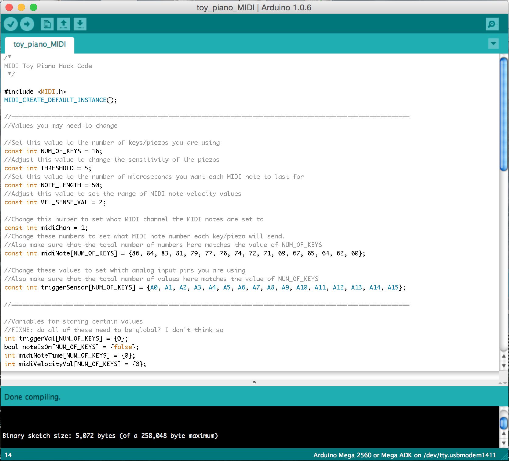
The Arduino software
Once you’ve copied the code into the application, complete the following tasks to compile the code into a program and upload it onto your Arduino board:
- Go to ‘Sketch -> Verify/Compile’, and as long as you have copied all the code and installed the MIDI Library correctly it should not come up with any errors.
- Connect your Arduino board to your computer via USB.
- Go to ‘Tools -> Board…’ and select the type of Arduino board you are using.
- Go to ‘Tools -> Serial Port…’ and select the option that starts with ‘/dev/tty.usbmodem’.
- Go to ‘File -> Upload’, and wait until it says ‘Done uploading’. Your Arduino board has now been programmed.
Please note – if you are going down the HIDUINO route, steps 4 and 5 won’t apply to you. Instead, connect your programmer to the Arduino as well as to a USB port, select the correct programmer from ‘Tools -> Programmer’, and upload to the Arduino using the ‘File -> Upload Using Programmer’ option instead.
Step 5—Connect the Software
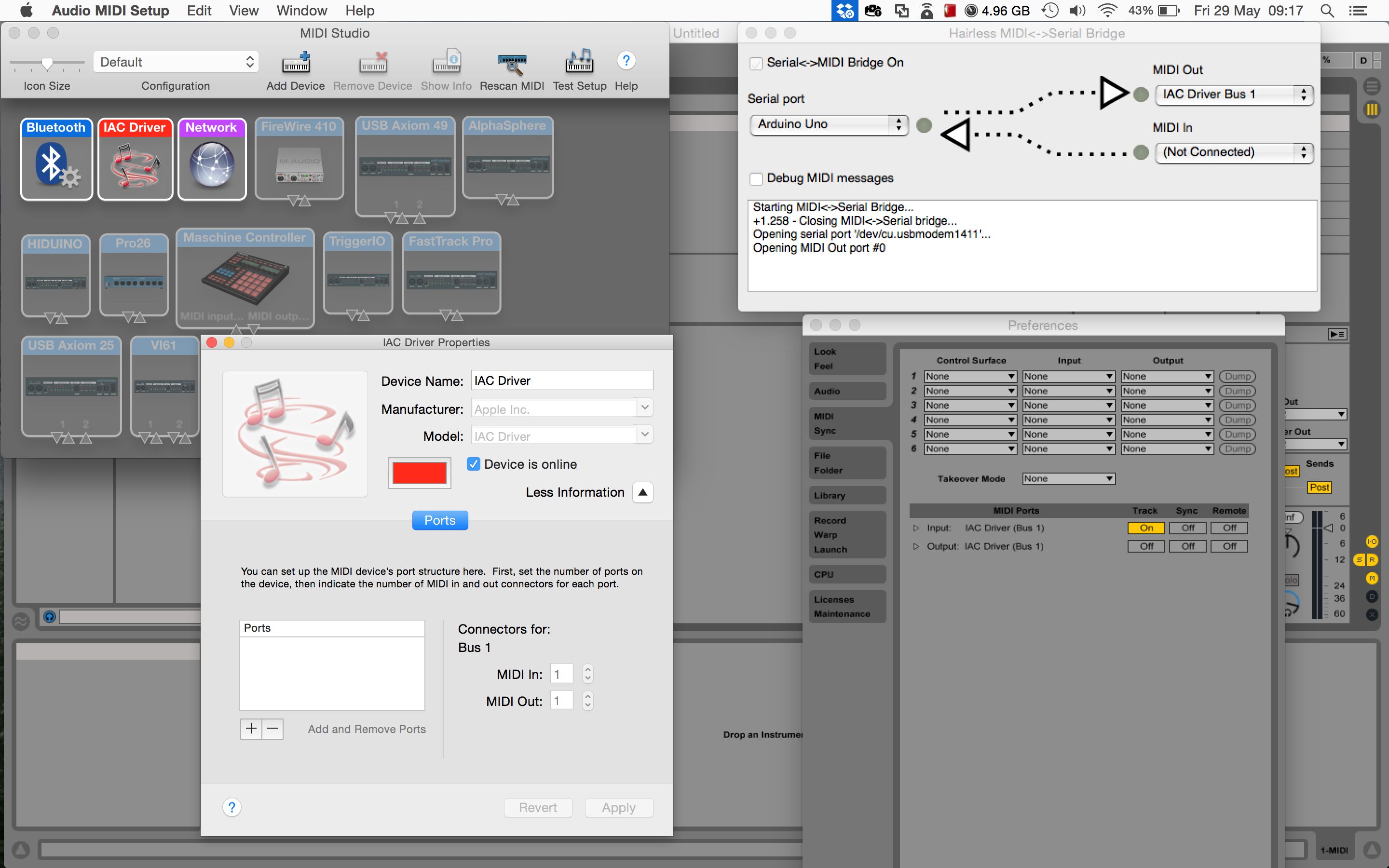
Left: Setting up a virtual MIDI port on OS X. Top-Right: Configuring Hairless MIDI to Serial Bridge. Bottom-Right: Connecting to the virtual MIDI port in Ableton Live.
Finally you need to launch and connect all the required software on your computer:
Set up a virtual MIDI port:
If you are on Windows:
- Open up loopMIDI
- Click on the ‘+’ button on the bottom-left side to create a new virtual port
- Leave the application running
If you are on OS X:
- Launch the ‘Audio MIDI Setup’ utility application
- Go to ‘Window -> Show MIDI Studio’ if the window isn’t currently being displayed
- Double click on the ‘IAC Driver’ object in the MIDI window
- Make sure that the ‘Device is online’ option is ticked
- Close the application
Connect Hairless MIDI-to-Serial Bridge to the Arduino and the virtual MIDI port:
- Launch Hairless
- On the left-hand side set the ‘Serial port’ option to be your Arduino board (its name will start with ‘Arduino’ or ‘/dev/tty.usbmodem’)
- On the right-hand side set the ‘MIDI Out’ to your virtual MIDI port (e.g. loopMIDI, IAC Driver)
- Make sure the ‘Serial MIDI Bridge On’ option is ticked
- Leave the application running
Connect you DAW/MIDI instrument software to the virtual port:
- Launch your DAW or MIDI instrument
- Under it’s MIDI settings, connect to the virtual MIDI port like you would connect to any other MIDI device.
Please note - if your Arduino is hacked with HIDUINO, steps 1 and 2 don’t apply to you. Instead the Arduino will just appear as a MIDI device called ‘HIDUINO’ which you can connect too within your DAW or MIDI instrument.
Once this has been completed you should now be able to trigger notes from your MIDI instruments with the toy piano.
Watch a short video demo of the acoustic toy piano MIDI controller in action:
Conclusion
So that’s how you can turn a wooden toy piano into a simple MIDI controller. This was only a very brief introduction to DIY electronics, software development, and the Arduino platform, so I recommend visiting the Arduino website if you want to delve deeper into this area.
Also, if you are interesting in taking part in the next MIDI Hack event, keep an eye on the MIDI Hack website for announcements. There are also a couple of similar music tech hackathons that are held annually all over the world, such as Music Hackday and Music Tech Fest, as well as various one-off and local events.

Discussion
You could connect a different type of sensor or electronic source and get results without changing the code, however it will only create a note based on the first reading it gets over the threshold (due to the logic implemented for turning piezo inputs into MIDI notes). Using just electrical current to trigger a reading would be very similar to using a simple push button (where pressing the button completes the circuit and creates a reading), so I'd recommend looking at Arduino button tutorials for that.
It sounds like your piezo sensors are not properly connected to the Arduino. Check that they are connected to the correct pins. You may also need to correct the value of NUM_OF_KEYS in the code if you are using less than 16 sensors/keys. You may also need to up the value of THRESHOLD in the code if your piezos are particularly sensitive.
thanks for answering me so fast , I'll check that the wires are connected correctly, I have another doubt about the code it in the end you said : "repeat the below code for each anaolog input/piezo sensor", and I 'm trying to do with a arduino uno with only 3 pins I changed all that you said , but the end I do not know where to get the code to be copied to each piezo I have and also do not know where it ends.
look I change this:
NUM_OF_KEYS = 3;
midiNote[NUM_OF_KEYS] = {86, 84, 83}
triggerSensor[NUM_OF_KEYS] = {A0, A1, A2}
IN THIS PART I WILL NEED TO PUT SOME NUMBER? -> (int count; count < NUM_OF_KEYS; count++)
Im sorry for all this question but im very lost with this and thank you so much for your help and sorry for my english.
Im from Brasil.
NUM_OF_KEYS, midiNote, and triggerSensor are the only values you need to change, which you have correctly done. The "repeat the below code for each anaolog input/piezo sensor" comment is actually a description of what the below 'for' loop does, rather than being an instruction. You shouldn't have to change any code in that section for it to work.
Thank you so much, this time again made ​​the piezos cables and worked, thanks for your help I buy one arduino mega
and when it comes I gonna do with the 16 piezos.
please let me ask you one more question?! can I put on this project potentiometers or one pitch bend?
Glad you got it working.
If you want to attach something like a potentiometer you'll need to change the code for reading from that particular analogue input. However the code needed here is a lot simpler - see https://www.arduino.cc/en/Tutorial/AnalogReadSerial to lean how to do this.
_____
#include
____
He's answering me this
#include
^
exit status 1
#include expects "FILENAME" or
Do you have an idea?
Thanks,
Florent
Thanks for the kind words and for spotting this mistake.
The code above has now been updated to the correct version.
Thanks,
Liam.
Project = allow young people to explore (play) the out-of-reach pipe organ from a wireless-midi capable keyboard.
So far... I have an arduino, a wireless midi transmitter/receiver (Medeli WIMIDI - tested and quite surprised by performance), a breadboard (cables, female midi socket etc).
I want to connect the wireless midi transmitter to the out socket of the remote keyboard and the wireless midi receiver to the arduino (I need to solder connect to arduino via breadboard). With the arduino midi library I presume I will then be able to receive the incoming midi signal ? This is where it becomes tricky for me to ascertain next steps!... I then want to translate the midi in to individual note signals (much like what you have done in this article). Is this possible?
If this is doable, my last sticking point is how to get the individual note signals 'transferred' to the organ console. I have seen an article where someone attaches a solenoid for each note to a wooden board and then rests the board over the top of the organ keyboard. However, the organ we are planning to work on already has access to the rear of the keyboard and each note has a visible switch (2 cables to each note) on a low voltage (12v) system. Is it possible to intercept each of these switches with the arduino outputs for each note? My apologies if this is a stupid question!?
This is an awesome tutorial. It'll help me a lot with what I want to do cause the setting is similar but usage is completely different.
I wonder if the amount of the contact mics can be different? Is there any maximum we can connect?
Also, is it possible to use condenser mics instead of piezos, possibly with a little trick?? Otherwise do you have any suggestions of how I can do it?
Thanks a lot!
The number of piezo sensors you can connect depends on the number of analog inputs that your microcontroller has e.g. on an Arduino Mega you have 16 analog inputs. However it is possible to expand this number using multiplexer components - see https://playground.arduino.cc/Learning/4051. There are also Arduino IO expander shields that can do this for you.
Regarding using consider mics instead, the extra complexity depends on whether you are just trying to detect a sound level, or trying to capture actual sound data. For just detecting sound levels see http://www.learningaboutelectronics.com/Articles/Arduino-microphone-circuit.php as an example, however recording actual audio is more complex (e.g. see http://www.instructables.com/id/Arduino-Audio-Input/).
Thanks a lot for your answer.
I have an Ard.Mega and I indeed only need to use them to retrieve vibration data - not sound.
Do you think I can use your setup the same, but differ the code to make it receive only vibration level - say from 0 to 100? In that case, would you mind sharing how the code shall be?
Many thanks.
I had a question. You used 18 piezo. But the Arduino mega allows only 16 input. What ambi missing?
""""const int THRESHOLD = {5,6,8,4,2,5,7,8,5,6};""""
What is the highest treshold value ?
Can you please tell me how i can separately change treshold, and limit the maximum & minumum velocity of each individual piezo?
If possible, write me another command line where i can adust the time amount for the gap between two stroke to avoid double triggering problem.
Thank you.
The highest value a piezo sensor can send using an Arduino is 1023, so threshold values could be anything up to this.
If you just want to 'clip' limit the velocity value, you could change the values on lines 'if (midiVelocityVal[count] > 127) midiVelocityVal[count] = 127;' to set a lower max value, and you could do the same kind of thing for the minimum limit e.g. 'if (midiVelocityVal[count] < 10) midiVelocityVal[count] = 10;'.
To limit how often a stoke can happen you could use the Arduino Millis Library (https://www.arduino.cc/en/Reference/Millis) to store a time for every stoke and then only process a new stroke if it's time is greater than the last time by a certain amount.
I saw padcycles in some sketch. I think it's about avoiding double triggering. I am not sure though. I tried Google. Didn't get enough learning about that term.
I have been playing my DIY arduino midi drum for a year.
your code works flawlessly. Recently i have decided to use a foot switch instead of using 2 separate pads for closed & open hat.
I use Arduino meda...Can you please guide me how the momentary switch should be wired to my arduino ?
And what modification i have to make into my current code for activating the switch functionality ?
My current Code is given below...
/*
Midi drum ..with 10 piezo.. no pedal(2 separate pad with 2 separate piezo for closed hat and open hat), Kick,snare, open hat, closed hat, tom1, tom2, tom3, crash1, crash2, ride
*/
#include
MIDI_CREATE_DEFAULT_INSTANCE();
//========================================================================================
//Set this value to the number of keys/piezos you are using
const int NUM_OF_KEYS = 10;
//Adjust this value to change the sensitivity of the piezos
const int THRESHOLD = 10;
//Set this value to the number of microseconds you want each MIDI note to last for
const int NOTE_LENGTH = 50;
//Adjust this value to set the range of MIDI note velocity values
const int VEL_SENSE_VAL = 10;
//Change this number to set what MIDI channel the MIDI notes are set to
const int midiChan = 1;
//Change these numbers to set what MIDI note number each key/piezo will send.
//Also make sure that the total number of numbers here matches the value of NUM_OF_KEYS
const int midiNote[NUM_OF_KEYS] = {36, 38, 60, 61, 49, 52, 48, 47, 43, 84};
//Change these values to set which analog input pins you are using
//Also make sure that the total number of values here matches the value of NUM_OF_KEYS
const int triggerSensor[NUM_OF_KEYS] = {A0, A1, A2, A3, A4, A5, A6, A7, A8, A9,};
//=======================================================================================
//Variables for storing certain values
int triggerVal[NUM_OF_KEYS] = {0};
bool noteIsOn[NUM_OF_KEYS] = {false};
int midiNoteTime[NUM_OF_KEYS] = {0};
int midiVelocityVal[NUM_OF_KEYS] = {0};
void setup()
{
MIDI.begin(MIDI_CHANNEL_OMNI);
Serial.begin(115200); //REMOVE THIS LINE IF USING HIDUINO INSTEAD OF HAIRLESS
}
void loop()
{
//repeat the below code for each anaolog input/piezo sensor
for (int count; count < NUM_OF_KEYS; count++)
{
//read the piezo value
triggerVal[count] = analogRead(triggerSensor[count]);
//if the value is over the threshold and there isn't currently a note on for this piezo
if (triggerVal[count] > THRESHOLD && noteIsOn[count] == false)
{
//get a velocity value based on the value
midiVelocityVal[count] = triggerVal[count] * (127.0 / 1523.0);
//increase sensitivity
midiVelocityVal[count] *= VEL_SENSE_VAL;
//make sure we don't go out of range
if (midiVelocityVal[count] > 127)
midiVelocityVal[count] = 80;
//send a MIDI note-on message
MIDI.sendNoteOn (midiNote[count], midiVelocityVal[count], midiChan);
//flag that the note is on
noteIsOn[count] = true;
//start a timer for the note to be on for
midiNoteTime[count] = NOTE_LENGTH;
}
//if the note is currently on
if (noteIsOn[count] == true)
{
//reduce the time value by 1
midiNoteTime[count]--;
//if time value equals 0
if (midiNoteTime[count] == 0)
{
//turn off the note
MIDI.sendNoteOff (midiNote[count], 0, midiChan);
noteIsOn[count] = false;
}
}
}
//pause the loop
delay(1);
}
I want to add a momentary switch as a foot pedal which will triggers note between 61 & 60 ( Closed & open HiHat). Thank You
Want to join the discussion?
Create an account or login to get started!