The gain knob of a preamplifier or console input section is simple in its usage. Rotate it clockwise to give more gain to the input signal and... well, that should be it, right? Yes, but while that is essentially what we do, there are details and gain knob markings that can confuse the uninitiated.
First off, one should realize that even on the largest or complex audio systems, no stage has greater gain potential than at this point. Most pre-amplifiers offer a minimum of 60dB of gain; giving this single knob more ability to boost the signal than all the other stages in a console or audio system combined. Some high-end or specialty preamps can deliver a whopping 80dB!
A Knob by Any Other Name…
While most device manufactures use the term Gain to label this knob, you can also find it marked Trim. This change of name has more to do with how op-amp works. Trim is the amount of negative feedback in the circuit, keeping the signal under control. Using a car analogy; turning the gain or trim knob clockwise is not giving the circuit more gas, it is actually removing the brakes (less negative feedback). Finally, in the Yamaha world of naming convention, this amplification circuit and the knob that controls the gain is often called the Headamp, and labelled HA on the device. This is because this is the amplification circuit at the head of the system. Potâto – Potáto, right? (sounds better than printed…). Mostly, yes. Gain, trim and HA (headamp) knobs all achieve the same outcome.
Many units have more than one input per channel and two are common - mic and line. Microphone sources usually require much larger increases of gain than do line level sources. On larger consoles, there may be two separate gain circuits (and thus, two knobs) that split the duties with one handling amplification for the low-level microphone input and the other for more beefy line-level sources. See figure 1.
While elegant and easy, this dual circuit solution is not the always the case, and it is the silk-screened labelling for a single-knob control that starts most of the confusion. There are a couple of ways that device makers handle this using one knob. The first may include a dedicated MIC/LINE switch that has the operator choose which source the pre-amp takes input. The other way is that by inserting a ¼” cable into the channel’s line input, the XLR signal is disconnected allowing only the ¼” signal to pass.
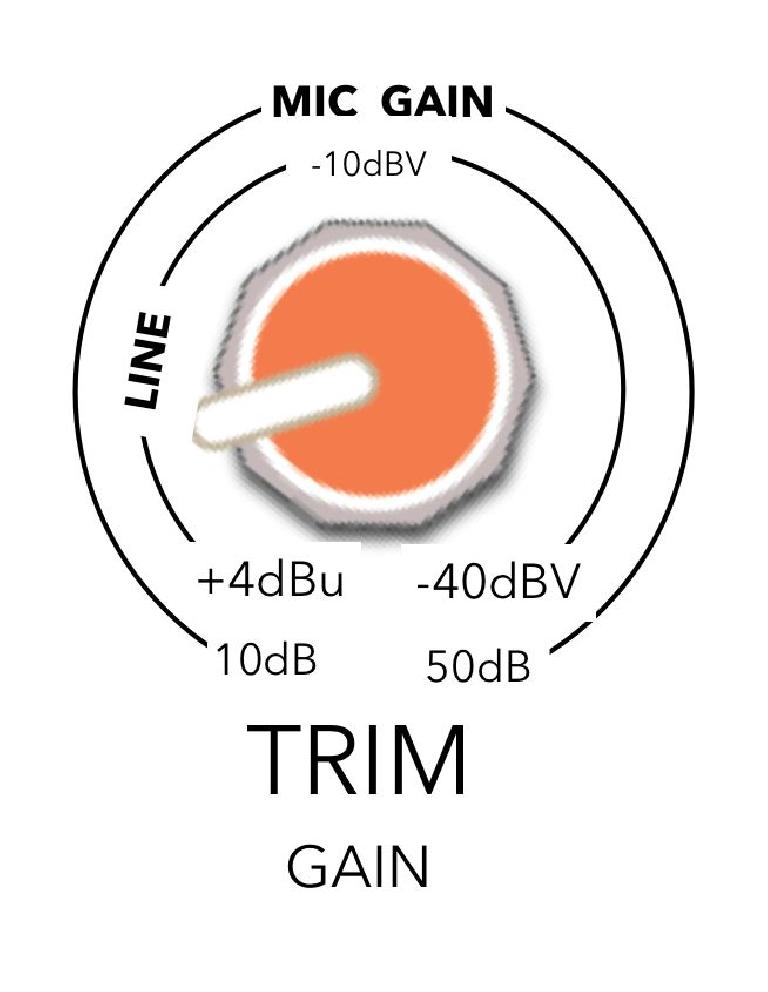
In both of these cases the line level signal is sent through a pad (around 20-30dB or so) before reaching the pre-amp proper. This is to prevent clipping from the much larger line-level signal. One can visually see from both figure 1 and figure 2 that having the gain knob turned to the fully ‘off’ position still allows around 10dB of gain to the incoming signal. This is why the incoming line level signal is reduced with the pad by default. For line level signals; adding 10dB of gain by default to a hot line level signal is recipe for clipping and distortion!
In a single-gain circuit approach, the gain knob will usually have two sets of markings; one for the microphone input and the other for the line-level input. See Figure 2. The outer ring shows the microphone gain in clear positive terms. But here is where things change a bit. The inner ring line level markings are references to the operating level of the device it is being sent FROM. The markings are saying “If receiving a signal from a +4dBu device, put the knob to the left, if from a -10dBV device put it at the 12:00 position.” In this case, there is no pad and if receiving a hot signal from a +4 device, it will clip the input of this channel.
Can we make it more confusing? Yes!
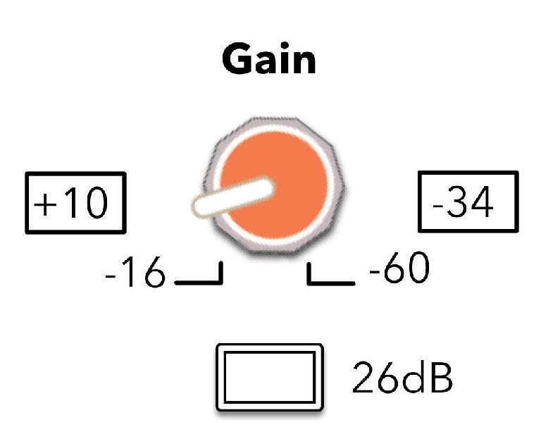
When analyzing the manner in which a device (such as shown in figure 3) displays its gain settings, one can end up confused. In this case, the positive numbers show up on the left side of the knob’s throw and the more negative numbers are found on the right. This seems opposite to logic. Seeing this for the first time can make one wonder; how can giving MORE gain be less?
Thankfully, on most consoles and preamps, the gain is shown as reference to the amplification gain in the circuit (as shown in figure 1 and outer ring of figure 2). It is amplifying by a certain dB amount, the goal being to get the incoming signal up to the operating level of the device or console (typically around 1.23V i.e. +4dBu). But Figure 3’s negative-on-the-right approach is the reverse logic! The markings are essentially saying “if the incoming signal is at ______ level, this knob setting will bring it up to the operating level of the device.”
This explains why the higher numbers are on the left of the knob, they are referencing the INCOMING signal and the labelling is saying “if you have a +10dBu signal coming into the circuit, put the knob way down here…” or “if you are coming in with a tiny microphone signal that is - 60dB (below) the operating level of this device, turn the knob way up here.” It’s one thing to do this with line level signals (since you would have a meter on the outputting/sending device), but to also do this with microphone inputs makes little sense. Seriously, who knows the difference between the device’s operating level and the voltage level of a microphone when the choir, guitar, or talent is at its average SPL output?
Conclusion
No, I don’t like it either. It really isn’t the most intuitive way of labeling the knob. But many devices like this exist in the wild and anyone who feels that they are qualified to run a console should understand what is being indicated. In figure 3 (from a Yamaha M3000a console) one can see that the line level and mic level signals are 26dB apart which correlates with the pad button below; the line level signal always runs through the pad. Depressing the button only works with the microphone input.
Since setting the gain for any input channel usually involves a meter displaying PFL (or at least a prefader channel mini-meter), setting the knob for the proper amount of gain is usually the simple affair that it should be. However, understanding the labelling and markings on each knob, fader or meter is the cornerstone of quality audio engineering.


 © 2024 Ask.Audio
A NonLinear Educating Company
Discussion
Want to join the discussion?
Create an account or login to get started!