
The McDSP Channel G bundle comes with three plug-ins, the G Dynamics, G Equalizer and G Console. In this article, I will go over the features available on the G Dynamics plug-in which has a filter, an expander/gate and a compressor/limiter with some really nice hidden analog emulation settings. The G console is basically a combination of the G Dynamics and G Equalizer, so you will be able to use all the features of the G Dynamics in the G Console plug-in as well.

McDSP's Channel G Dynamics Plug-in.
Signal Path
The signal flow can be viewed by clicking on the 'SIG' switch on the top-left part of the interface. Each of the three processors (filter, expander/gate, compressor/limiter) can receive input from multiple sources indicated by the 'KEY' switch control in the lower part of the interface, though for the filter it's called 'FILTER INPUT'. Key is more of a dynamics processor term so it makes sense not to call it that for the filter. Changing the input on each processor will be visually indicated in this area.

The Signal Path.
The four main sources available for each processor are:
- IN - This is the unprocessed sound taken from the Insert point of the track in your DAW. In other words, the original input. In the Signal Path view, this is indicated by the lower bar that starts with a speaker icon and ends with the text 'AUDIO OUTPUT'.
- Key icon - Choosing this will select the side-chain input to the insert. Setting up a sidechain input will differ on each DAW, but in Pro Tools you can select it via the 'Key' drop-down menu just above the controls of the plug-in, which also happens to have a similar key icon. This may not be the same in other DAWs. The Key signal is shown as a bar on the top part of the Signal Path view. This will usually be lit blue if there is a signal detected.
- F - This is the signal output from the filter. Barring the filter, both the other processors can receive the signal from here. The Signal Path will also show this visually by piping a connection from the Filter to either of the two processors.
- Feedback icon - This is exclusive to the Compressor/Limiter. Selecting this switch sets the compressor in feedback mode rather than the more standard feedforward mode. Feedback compression is more common on older hardware VCA compressors but can also be seen in newer compressors like in the Neve Portico series.
In the feedforward mode, the VCA control voltage (the voltage that detects if the signal needs to be compressed or not) is taken at the input or the source. In feedback mode the control voltage is taken at the output. So in a way, the signal has already passed the VCA before it gets compressed. This results in a smoother, more musical compression versus the more accurate but harder compression with the feedforward design.
When the feedback mode is enabled, it is also graphically represented in the Signal Path view.
The Filters
The low and high cut filter occupy the lower part of the interface. Both the filters have the usual frequency & slope controls. The frequency is fully sweepable in the range of 20 Hz - 20 kHz. The slope knob works as a Q control when the filter is set to a notch filter. Each filter also has its own individual ON/OFF switch indicated by the small green LED next to it, which is also seen on the other two processors. You can see the effect of the filter in the graph which can be enabled by clicking on 'GPH' at the top left part of the interface.

The Low cut and Hi cut filters.
The filters can be applied on the audio signal and sent to the output, though to do this, in the FILTER PATH, the 'INLINE' switch should be enabled.
Another use of the filters is to filter out certain parts of the audio before it goes to the expander or the compressor. To do this you will have to choose 'F' in the KEY option for the expander or the compressor and switch OFF 'INLINE' so the filtered audio is not heard. This is great for when you want to compress drums but do not want that pumping sound. So filtering out the low frequencies and using that signal to key the compression can avoid the pumping effect as only the mid and high frequencies will trigger the compressor and the low kick drum sound won't trigger the compressor.
The Expander/Gate
There is no dedicated switch for the two modes of this processor but the expander or gate functionality will depend on the Ratio and Range parameters. A ratio of 1 will have no effect on the audio, while any ratio higher than that will work as an expander or a gate. Generally if the audio is completely attenuated, the processor is a gate while if the audio is not completely attenuated, it is working as an expander. This can completely depend on the program material, but I've noticed a ratio of 30:1 or higher sounds like a gate.
The RANGE defines the amount of attenuation. So a setting of 0 dB will have no effect on the audio and anything lower will attenuate the sound, assuming the sound has dropped below the THRESHOLD value. For subtle expansion, use a value of negative 30-40 dB, anything lower will start to sound more like a gate. At the lowest value of -80 dB, you will get a hard gated type sound, assuming the ratio is set relatively high.
The ATTACK defines the onset time of the effect while the RELEASE parameter controls the time it takes to return back to unprocessed levels. The HOLD parameter can keep the effect on for a little while longer even if the signal has crossed the THRESHOLD. This can be helpful to avoid the zipper noise effect caused by using really fast attack and release times.
The effect is also visualized in the input/output transfer function graph which can be accessed by clicking on the 'GPH' switch.

Expander / Gate.
The Compressor/Limiter
Just like the Expander/Gate, this processor doesn't have exclusive controls for the two modes. Primarily, the ratio will define whether its running as a compressor or a limiter. Generally speaking, anything over 20:1 is considered limiting. Anything less than that will be within the compression range, though a ratio of 1:1 will have no effect on the audio. The ATTACK and RELEASE work the same way as in the Expander/Gate while the threshold works exactly the opposite. So a signal will only be compressed if it crosses the THRESHOLD, anything below that will remain unaffected.
The KNEE is a very interesting parameter. It defines how immediate or gradual the ratio settings can be. Broadly speaking, there are two knees (no pun intended!), hard and soft. In the hard mode, the compression ratio is implemented as soon as the signal crosses the threshold. This is what is normally expected, but in the soft knee mode, the compression ratio is gradually increases to the chosen value, resulting in a more smooth compression. This setting along with the attack time can really shape the compressor's onset. In Channel G Dynamics, the lowest value of the KNEE knob gives a hard knee setting while anything above that emulates a soft knee setting. You can see the effect of the knee visualized on the input/output transfer function graph in the 'GPH' area. The compression curve gets more 'curvy' as the knee is increased.
Above 100 on the knob, things get a bit more interesting. McDSP has included four knee curves that emulate vintage analog compressors. The 'Chan' and 'Buss' mode emulates the channel & buss compressor from an SSL console. The 'Brit' mode emulates a Neve 33609C stereo buss compressor. The 'A Soft' and 'A Hard' emulates an API 225 compressor in soft and hard knee modes respectively. You will also notice that the ratio, attack & release knobs will limit their ranges to match the device being emulated. In fact even the filter's cutoff frequency range will be limited depending on the chosen emulation.

Compressor / Limiter.
Console Meters
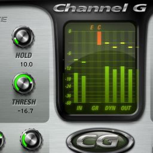
The meters on this plug-in are quite comprehensive. The two leftmost meter's show the input level(IN) of the signal which can be controlled with the 'IN' knob located at the top left corner of the interface. The next two meter's show the expansion and compression gain reduction(GR) respectively. They are labelled 'E' and 'C' for convenience and have an orangish glow to them as opposed to the greenish-yellow look of the other meter. The next two meters show the output from the compressor stage and the last two meters show the output of the entire plug-in, which is after the final gain stage which can be controlled with the 'OUT' knob on the top right of the display. The meters will peak red if they reach -0.05 dB, so technically the signal hasn't quite peaked yet even if the peak LEDs are lit red.

Console Meters.
So, that's an overview of a really excellent plug-in from McDSP that can be quite clinical in operation but at the same time, very non-linear and analog sounding especially with all the knee settings.

Discussion
Want to join the discussion?
Create an account or login to get started!