The Anatomy of Balanced vs. Unbalanced Cords
Before we can get into the difference between the two types of cords, we need to understand what is inside them.
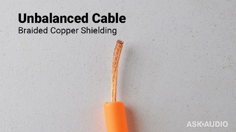
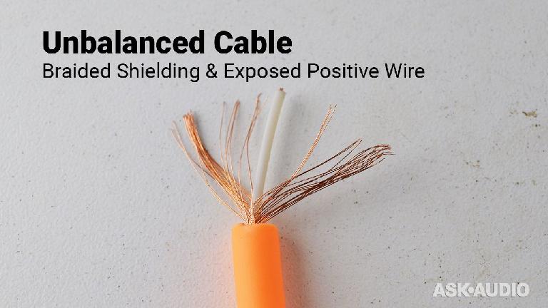
Once you remove the outer plastic housing from an unbalanced cord, you will run into what is called a “Braided Shield”. That is a mesh of copper wires wrapped around a single smaller signal wire. There are a few different forms of braids. There are single, double and French braiding styles. Each has a different effect of incoming noise.
If you are going to make or repair an unbalanced wire, you will need to gently gather those loose wire strains and twist them together.
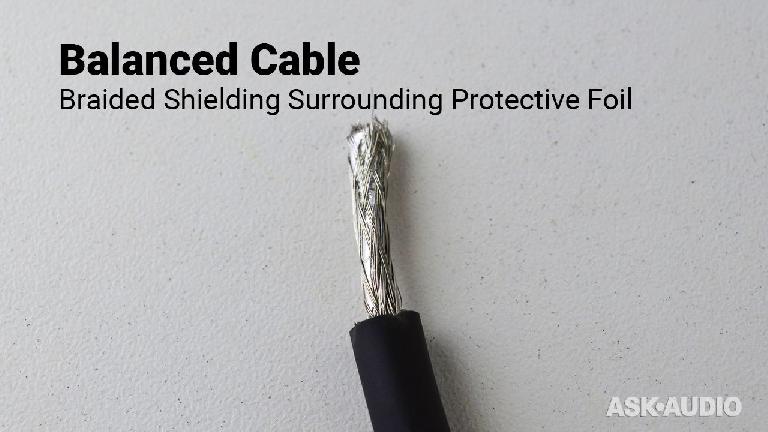
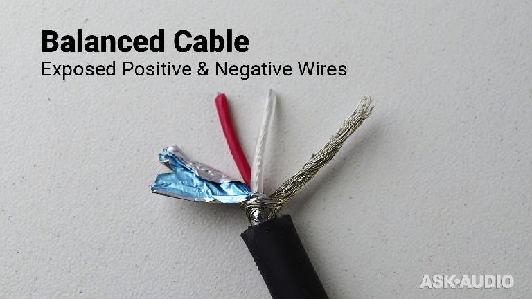
Balanced cables have a bit more inside. After removing the outer plastic layer, you might encounter one of two things. The cord, depending on quality, might have just a braided shield, like that of the unbalanced cord above, but it also might have another foil shield for double the protection, like the picture below.
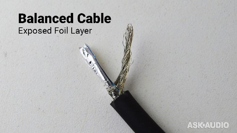
Here is the same wire with the braided shield gathered and twisted together giving you a better look at the foil.
Once you gently pull the foil over to the side, you will notice that a balanced cable has two signal wires. These are positive, sometimes called “hot”, and negative signal wires. Not to be confused with stereo wires, like RCAs. Those are two unbalanced cables joined together.
When to use Balanced vs. Unbalanced Cables
Both cables have what is called shields. These are meant to stop outside noise from interfering with the signal wire(s) inside. There are two types of noise that are likely culprits trying to mess up your otherwise perfect audio signals.
Radio Frequency Interference (RFI) & Electro-Magnetic Interference (EMI). If you are hearing high frequency noise it is probably RFI, and if the frequency is low you have some EMI.
For short cable runs, 15–20 ft or less, instrument and line level audio unbalanced cables usually do the job. Think guitar & speaker cables. Those two signals are strong and the short distances reduces the chance of outside interference. However, not playing near radio towers or placing power cords on top of the cables is good practice too!
Long cable runs and mic level audio signals are more susceptible to noise. Mic levels are very weak and easy to mess with. That is why, in most cases, microphones should be using balanced cables.
Obviously, of our two cables above, the balanced one already has the advantage of having two shields. But that isn’t even the best and most effective defense against noise.
How do Balanced Cables Work, and Why They’re Awesome!
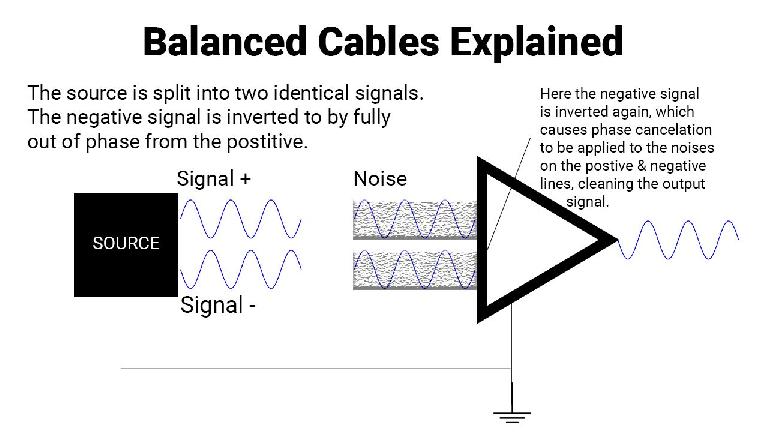
The genius of balanced cables works like this. When the audio source is fed into an XLR, for example, the negative signal wire inverts the phase of the audio signal. So, immediately you have two identical audio signals traveling over the cables out of phase with one another.
Let me explain what that means quickly.
Let’s say you have two channels. Channel one has some audio, which exists in waveform, as all audio does. Then you take that exact waveform and duplicate it onto channel two. The output signal would be doubled. However, if you take that second audio waveform, invert it and the play it at the same time as the original you won’t hear anything. There would be silence. That is because the waveforms are canceling each other out.
Now, back to our balanced cable. The two identical out-of-phase signals are traveling over the wire. Let’s imagine some noise getting introduced after being dulled by the two shields. The cool thing is that the noise will be applied equally and identically to both the positive and negative signals.
Upon passing through the second XLR connector the negative signal is inverted again, but, now it is just adding to the positive signal.
This is where the magic happens.
The noise in the negative signal wire is also inverted at that time. That noise that is identical to the noise in the positive signal wire. That means the noise that was introduced along the cable run cancels itself out while the audio signal is allowed to pass through.
Is that not ingenious?


 © 2024 Ask.Audio
A NonLinear Educating Company
Discussion
The correct spelling is "cords" as in "power cords".
At the end, when the negative signal is inverted again, I understand the noise will be cancelled, but wouldn't the original signal be now doubled since it is inverted back on the negative signal?
So as I understood, they are not really split into 50/50. they are really 100%/100%, doubled if not inverted / totally cancelled if inverted. So, in the end, inverting back one of the channels and adding one to another, by logic, will make the result doubled. Or am I missing something? :)
See this image with my idea: http://i65.tinypic.com/ioi7g1.png
Thanks
Want to join the discussion?
Create an account or login to get started!