
A NonLinear Educating Company
Make Your Own DIY 3D Gesture and Tracking USB MIDI Controller
Liam Lacey on Sep 17, 2017 in DIY & Hacking | 8 comments
Over the past ten years or so there have been a growing number of consumer products and sensors brought to market that allow 3D gesture and motion tracking for controlling computers, games consoles, and other electronic devices. These include camera-based devices such as the Microsoft Xbox Kinect or the Leap Motion Controller; accelerometer/gyroscope-based devices such as the Nintendo Wii Remote or the Apple iPhone as well as completely novel devices such as the EMG-based Thalmic Labs Myo armband or the Radar-based Project Soli sensor by Google.
The majority of these devices - whether officially or through hacks - can be used to control music software; applications such as Geco MIDI for the Leap Motion Controller or Leviathan for the Myo allow these devices to be turned into expressive gesture and motion sensing MIDI/OSC controllers. There are also a few purpose-built gesture-based music controllers such as the mi.mu gloves, the Percussa Audiocubes, or the Source Audio Hot Hand.
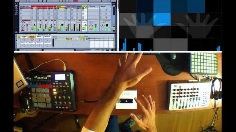
Leap Motion Controller and Geco MIDI in action. Source: https://www.youtube.com/watch?v=PcAfUXfGes0
However, thanks to the recent development of the Microchip MGC3130 gesture and tracking chip, a number of new affordable sensor boards are being introduced that allow you to create 3D hand gesture and tracking devices with ease and for less than $40. One range of these sensor boards is the Pi Supply Flick range – a set of surface-mountable boards that can detect seven different specific hand gestures as well as 3D XYZ tracking within a range of 15cm, which also have touch sensing for 15 different types of touches. While most of the Flick boards are designed to attach to Raspberry Pi boards, there is a standalone Flick board which can connect to any other I2C enabled microcontroller or microprocessor such as Arduino, Teensy, or BeagleBone.
In this tutorial I’m going to show you how to build a Flick-based 3D gesture and tracking USB-MIDI controller in conjunction with a Teensy microcontroller. Teensy is in my opinion the best platform for building your own USB-MIDI controllers due to its low price, its ease of use, and its flexibility. While the Flick sensor boards aren’t as advanced or feature-full as some of the existing gesture and tracking devices, there are a number of reasons why you may want to build your own DIY device using Flick and Teensy:
- 1. It’s cheap. Flick sensor boards cost between $25-40, while the affordable Teensy LC board is just under $12.
- 2. It will be a class-compliant USB-MIDI device, meaning it will work with any current or past OS that supports MIDI - including iOS and Android.
- 3. It won’t require any middleware software to be running, unlike with the Leap Motion Controller or Myo.
- 4. All gesture sensing processing is done on the sensor chip rather than the computer/device it is connected to, meaning it can work with low-spec computers.
Here is a video example of what we’ll be building – a USB-MIDI controller that sends different CC messages for detected hand gestures, or a set of three CC messages for a hands XYZ position, switchable via a touch of the sensor. With this particular demo using Ableton Live and the Sugar Bytes Turnado plug-in, I’m using the swipe/flick gestures to change drum loops (quantized to Live’s clock); the X position to change the filter cutoff; the Y position to change the tonalizer mix; and the Z position to change the bitcrusher mix.
A demo of the DIY 3D gesture and tracking USB-MIDI Controller:
What You Will Need
- A Teensy board. I’ll be using the budget Teensy LC, however you could instead use the Teensy 3.2, 3.5, or 3.6. Make sure you get a Teensy with pins, unless you fancy soldering them on yourself.
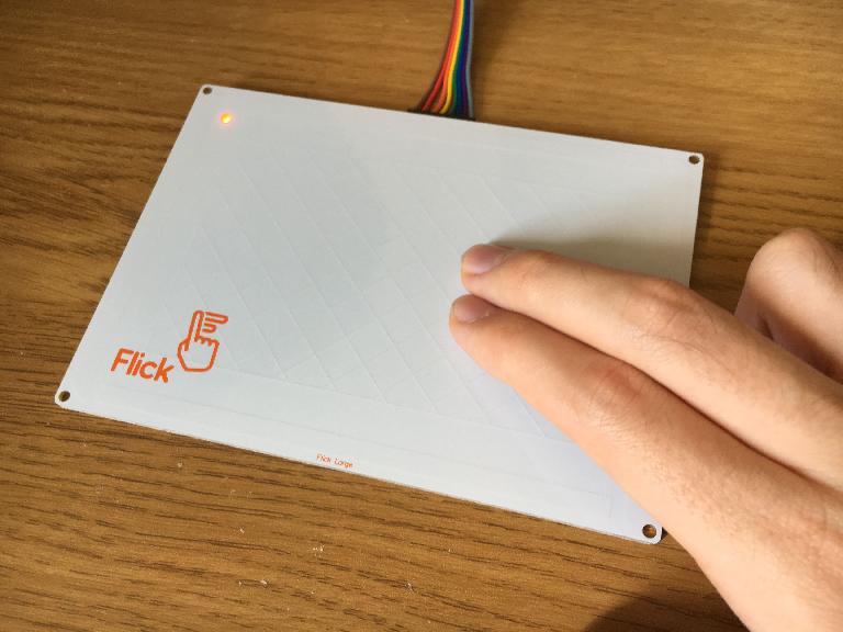
- Flick Large Standalone sensor board (and the supplied female-to-male jumper cable)
- A solderless breadboard
- The Arduino IDE software
- The Teensyduino software
- The Skywriter Arduino Library
- USB Micro-B cable
Step 1 – Connecting Flick to Teensy
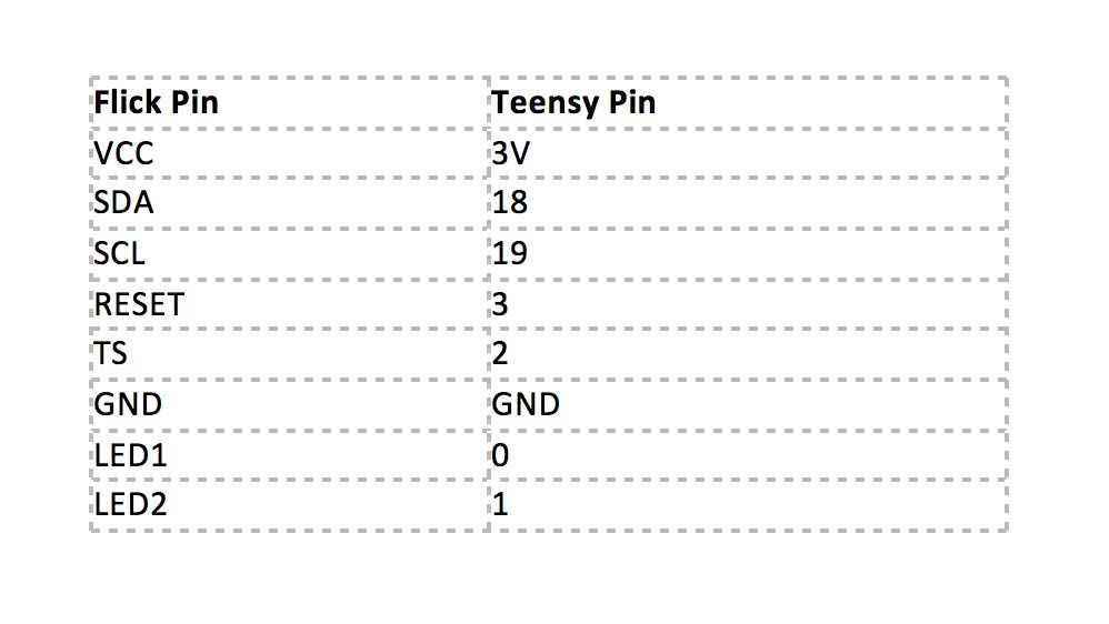
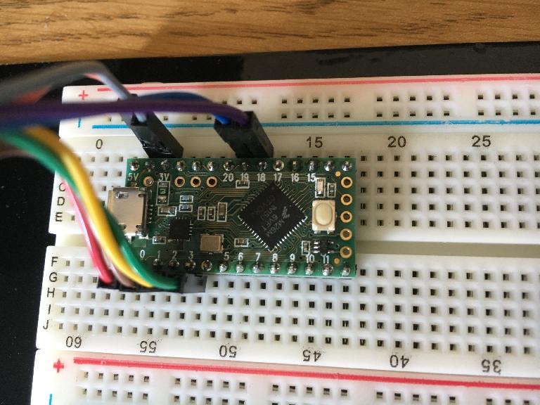
First lay your breadboard horizontally and place the Teensy over the middle divider of the breadboard. Next attach the female side of the jumper cable to the pins on the underside of the Flick board; the orientation doesn’t matter, however I’ve got the grey wire on the left and the brown wire on the right. Finally, connect the male side of the jumper cable to Teensy (via the breadboard) using the following pin connections:
Step 2 – Installing Software
To develop for Teensy you need to download and install two pieces of software:
Once they have been installed you then need to install an Arduino library that allows the Flick sensor board to communicate with the Teensy board. At the time of writing the Flick Arduino library has yet to be released, however the Pimoroni Skywriter Arduino Library is officially supported by Flick. Download the library from here, and install it by placing the ‘arduino/Skywriter’ folder into the ‘Arduino/libraries’ folder on your computer (usually found in your Applications/Programs directory).
Step 3 – Writing And Compiling Code
Once all software has been installed complete the following steps:
1. Connect the Teensy board to your computer via the USB cable. If it is a brand new Teensy the onboard LED may now be flashing.
2. Launch the Arduino application.
3. Go to File -> New to open a new Arduino project.
4. Write the code - Replace all the text in Arduino’s text editor with this code.
5. Go to Tools -> Board and select the specific Teensy board you are using. If you cannot see the Teensy board section go back and make sure you correctly installed Teensyduino.
6. Go to Tools -> USB Type and select ‘MIDI’.
7. Compile the code - Go to Sketch -> Verify/Compile, or instead just click on the tick icon on Arduino’s toolbar.
8. If no errors appear in the console pane at the bottom, the Teensy software window should pop up. If this did not happen and errors appeared, go back to point 1 and carefully follow the instructions again.
9. As stated in the Teensy software window, press the button on the Teensy board to put it into Program mode. The LED should no longer be flashing.
10. Upload the code to the Teensy board - In the Arduino software go to Sketch -> Upload, or instead just click on the arrow icon on Arduino’s toolbar.
11. If the upload is successful the Teensy software will show a progress bar followed by ‘Reboot OK’, and no errors will appear in the Arduino console pane.

The Arduino software configured for Teensy USB-MIDI development
Step 4 – Testing And Using The 3D Gesture MIDI Controller
Now you are ready to test your DIY MIDI controller. Open up your DAW/MIDI software of choice, and connect to the MIDI device called ‘Teensy MIDI’ (or something similar). I have programmed this controller to work and be used in the following way:
- The controller has two modes – ‘Gesture’ mode and ‘Tracking’ mode. To switch between them, touch on the bottom panel of the Flick sensor.
- If the Flick board LED is red, it is in ‘Gesture’ mode. Here you can perform seven different gestures which each send a different MIDI CC message:
- ‘Garbage throw’ gesture – sends CC 101
- Flick west to east – sends CC 102
- Flick east to west – sends CC 103
- Flick south to north – sends CC 104
- Flick north to south – sends CC 105
- ‘Airwheel’ gesture (clockwise and anticlockwise) – sends CC 7
- Out of the above gestures, the first five toggle between CC values 0 and 127, however the airwheel gesture sends a continuous value between 0-127, changed by the direction and speed of the gesture.
- If the Flick board LED is green, it is in ‘Tracking’ mode. Here the sensor will track the position of your hand in 3D space, and send the following CCs with values between 0-127:
- X position – sends CC 72
- Y position – sends CC 73
- Z position – sends CC 74
- Tapping the left, top, and right panels of the sensor will send a single CC for the X, Y, and Z mappings respectively. This is useful for when wanting to easily map the three tracking CCs to controls within your DAW.
Next Steps
The next thing you may want to do is add your own customizations to the behaviour of the DIY MIDI controller, such as changing the CC numbers, ranges, or entire MIDI messages that the gestures and tracking positions create. All of this can be done within the Teensy code that you compiled and uploaded above; while teaching you how to code is a bit beyond the scope of this tutorial, I’ve placed many comments (lines beginning with ‘//’) in the code to describe what each part is doing, in the hope that it will help guide you in any modifications you want to make. For example, changing the number at the end of the ‘#define MIDI_CC_X 72’ line will change the MIDI CC number that X position tracking will generate.
Conclusion
So that’s how you can build your own 3D gesture and tracking USB-MIDI controller using a Flick sensor board and a Teensy microcontroller. While it may not be able to do everything that existing gesture and tracking devices can do, you’ve built a standalone, class-compliant USB-MIDI controller that can be fully customized for your needs and for not a lot of money, and something that could potentially bring a new level of expression and inspiration to your music composition and performances.

Discussion
Just need to put the pins correctly and it's done?
Want to join the discussion?
Create an account or login to get started!