Consider these the very first steps in hard synth prototyping and construction. We are going to make some noise via a basic circuit. We are also going to add a knob that we can turn to change the pitch of the sound. The final result isn’t breathtaking, but the journey will be inspiring and informative for those looking to moonlight or dive into hardware synth development.
For the most part, I am going to be glossing over what each of these components actually does behind the scenes, as each would require their own tutorial, but if you do a simple Google search for the keywords you find a deeper understanding of them. My goal here is to get you up, running and excited about the possibilities!
What You Need
Materials: (less than $10, assuming you have a breadboard)
- Breadboard
- 555 Time IC (Integrated Circuit)
- 10uF Capacitor 25v +
- 1uF Capacitor 25v +
- 330 Ω (Ohm) resistor 5%
- 100k Variable Resistor (Potentiometer)
- 8 Ohm Speaker (15 Watt is good)
- 9 Volt battery
- 9 Volt connector
- A decent length of wire
- Various resistors between 1,000 (1k) and 33,000 (33k) (optional)
Tools:
- Wire cutters
- Tweezers (optional)
The Process
Important: connecting the power supply should only be done last for your safety and to protect the components of the circuit. Also, when prototyping it is best to use low voltages to avoid serious injury.
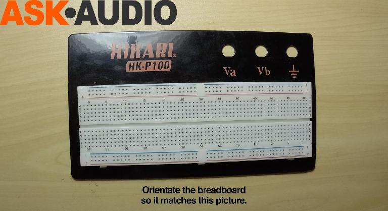
Hopefully you are familiar with a breadboard (protoboard). It looks like the picture below. They come in a range of sizes but are all set up the same way.
The main circuit routing happens in the middle in rows A–J and the columns 1 - ?. This board has 30 columns, but there are various sizes available. The power source(s) are fed to the lanes on the outside which are colored red (+) and blue ( - or ground).
Place your breadboard on the table in front of you so that it looks just like this picture. The colors from top to bottom should go blue, red, blue, red. This will help us stay organized and on the same page.
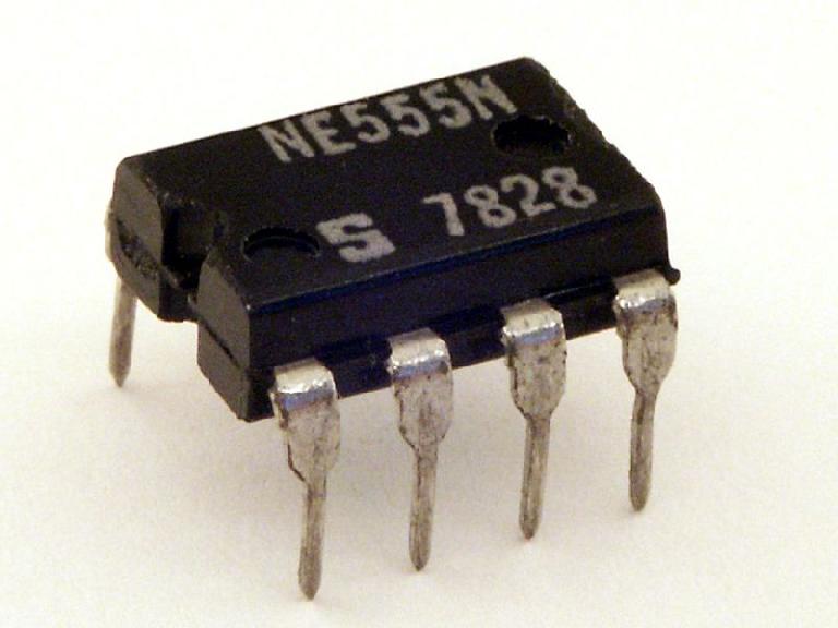
The 555 timer IC is an integrated circuit (chip) used in a variety of timer, pulse generation, and oscillator applications
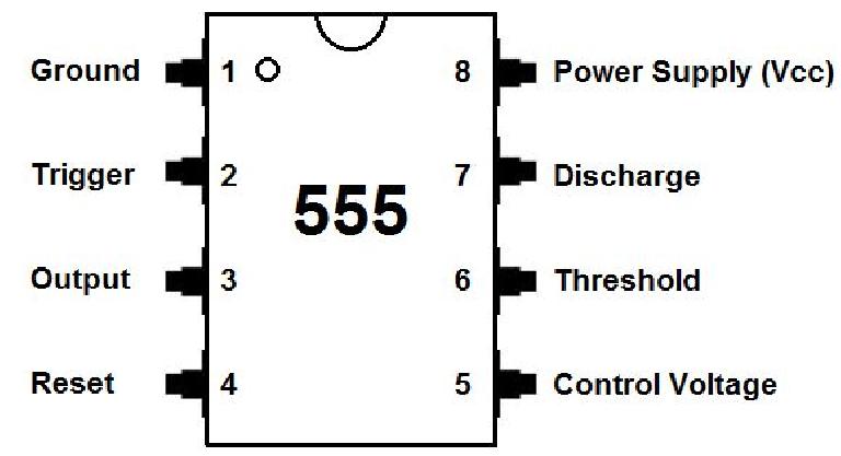
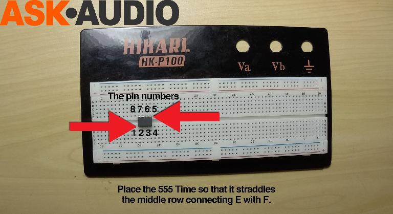
The first step is to place the 555 Timer somewhere on the board so the it stratles the middle lane. The 555 Timer IC has a small notch on the top and to one end. There may be other small circular indentations, but the one at one end is the one we are looking for. The indicates the 1 & 8 pins. We want the 1 pin to be closest to us and on the left.
Each of the 555 Timer’s pins has a set function. We need to set out connecting them to each other, the speaker, the Variable Resistor and the Power Source to create what is known as a circuit.
URL: https://en.wikipedia.org/wiki/555_timer_IC
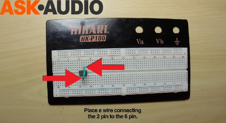
It is easiest to start close to the 555 Timer and work our way out. So, let’s place a short wire connecting the 2 pin to the 6 pin. The colors of the wires don’t matter, but when the projects become more complicated it might be best to have a system. We dealing with the power source I would suggest using red for positive (+) and black for negative ( - ). However, for these inner connections you can use any color you like.
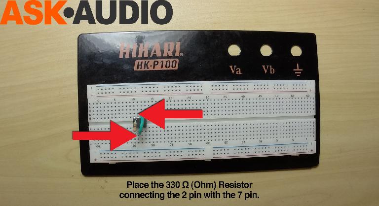
Now we need to connect the 2 pin (trigger) to the 7 pin (discharge) with a 330 Ω (Ohm) resistor. Which has a color code of Orange-Orange-Brown-Gold.
All resistors have color codes unique to their values.
URL: https://en.wikipedia.org/wiki/Electronic_color_code
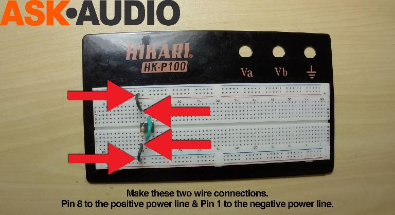
Now we will knock out two similar steps. Get to short wires. Use one to connect the 1 pin (ground) to the negative power line (ground). Use the other to connect pin 8 (power supply) to the positive power line.
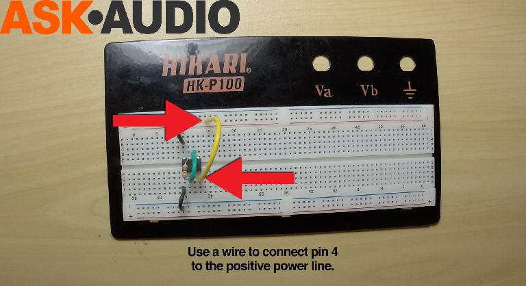
Take a slightly longer wire and connect the 4 pin (reset) to the positive power line.
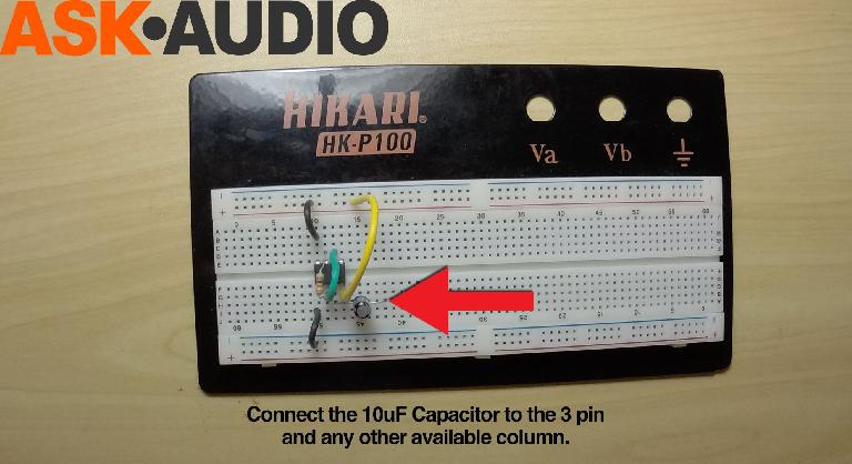
This 10 uF capacitor is polarized, meaning it has a negative and positive side. The negative side is marked with the grey stipe and the negative symbols. Also the positive lead will be longer. We need to connect the positive lead to pin 3 (output) which is where we want to current to leave the circuit and go to the speaker. We can now place the negative lead in any free column.
URL: https://en.wikipedia.org/wiki/Capacitor
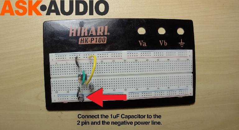
This 1 uF capacitor is also polarized. Connect the positive lead to pin 2 and the negative lead to the negative power line (ground).
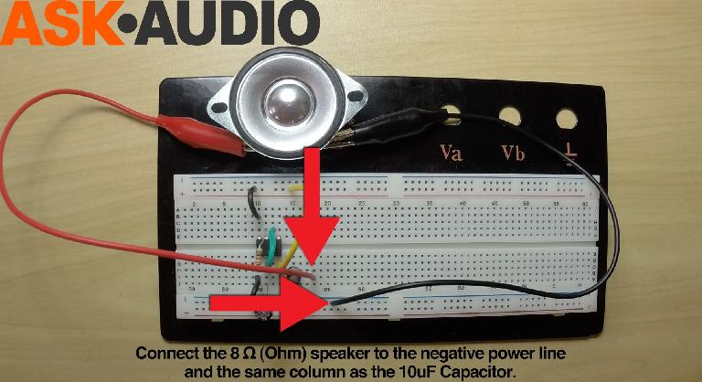
The speaker I am using is an 8 Ohm 25 Watt. It is also polarized. I am simply attached one sided alligator clips to the positive and negative connectors. Then I connected the negative to the negative power line on the breadboard. The positive wire needs to go in the same column as the negative lead of the 10 uF capacitor.
The next step is to add the variable resistor (VR), also called a potentiometer. I chose to use this to add a bit of flair to your first project, but as the name suggest you can use a regular resistor in its place.
Different resistor values will generate different pitches. After you have completed this project you should come back to this step and replace the VR with different resistors between 1,000 (1k) and 33,000 (33k).
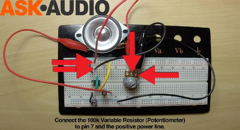
Here I am using one sided alligator clips attached to the VR. The negative wire is going to pin 7. The positive wire is going to the positive power line.
URL: https://en.wikipedia.org/wiki/Potentiometer
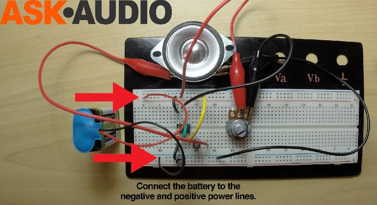
Now we connect the 9v battery’s negative power wire to the negative power line on the breadboard. Then the battery’s positive to the positive power line. You should immediately hear a buzzing sound. Now you can move the potentiometer and you will hear the pitch changing.
Learn about synthesis in the Ask.Audio Academy here.


 © 2024 Ask.Audio
A NonLinear Educating Company
Discussion
Can I also use the NE555P Instead of the NE555N ?
Thanks..
It seems that they just have different manufacturers.
Here are the datasheets for both if you are interested in going further down the road ...
http://datasheet.octopart.com/NE555N-STMicroelectronics-datasheet-503160.pdf
http://datasheet.octopart.com/NE555P-Texas-Instruments-datasheet-148786.pdf
I was able to complete it with no electronics knowledge. I'm gonna add a 'killswitch' to mine to vary the note lengths!
QUESTION...does anyone know what kind of wave this produces? Sounds like square to me, but I don't have a great ear for that.
Want to join the discussion?
Create an account or login to get started!