High Pass Filter
I mentioned earlier that we will be creating a very basic high pass filter that will filter out lows (if required) before the signal is sent through the low pass filter. Let's now create this.
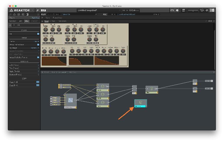
Double-click anywhere in the background of the structure view to get out of the Filter macro. Right-click in the background of the structure view and select New Macro. Double-click the name of the macro and rename it to High Pass.
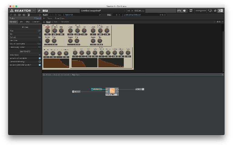
Double-click on the macro to enter its structure view. Right-click in the background of the structure view and select Built-In Module > Filter > HP/LP 1-Pole. This is a dual mode 6 dB/octave filter. Right-click in the background of the structure view and select Built-In Module > Terminal > In Port & Built-In Module > Terminal > Out Port. Connect the In to the In of the Filter and the HP out of the filter to the Out. Set the range of the newly created P Cutoff Dial to 0 to 127. (Image 49) This will give it a nice and wide range so when the parameter is at its lowest, its equivalent to being off. Rename the P Cutoff Dial to Cutoff.
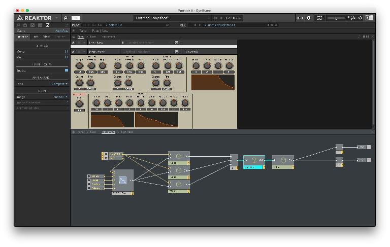
Double-click in the background of the structure view to get out of this macro. We need the high pass to work before the main filter, So connect the Add module’s output to the In of the High Pass and connect the Out of the High Pass to the In of the Filter.
The Panel view now will have the High Pass macro with the Cutoff dial. Hit Command-E to edit the panel view & move the macro away so there is no overlap and the layout looks more intuitive.
Lock the panel & test the high pass. Make sure the signal gets filtered. If its not working, make sure the connections are correct by reviewing this section. If everything is working as it should, make sure to save the ensemble!
Distortion Effect
We have a pretty functional synthesizer so far, but adding some effects will take it to the next level. Let's now see how to create a distortion effect section.
Rick-click and select New Macro. Double-click the name of the macro and enter Distortion, then Double-click on the macro to enter its structure view. We will be creating all the elements of the distortion effect inside this module.
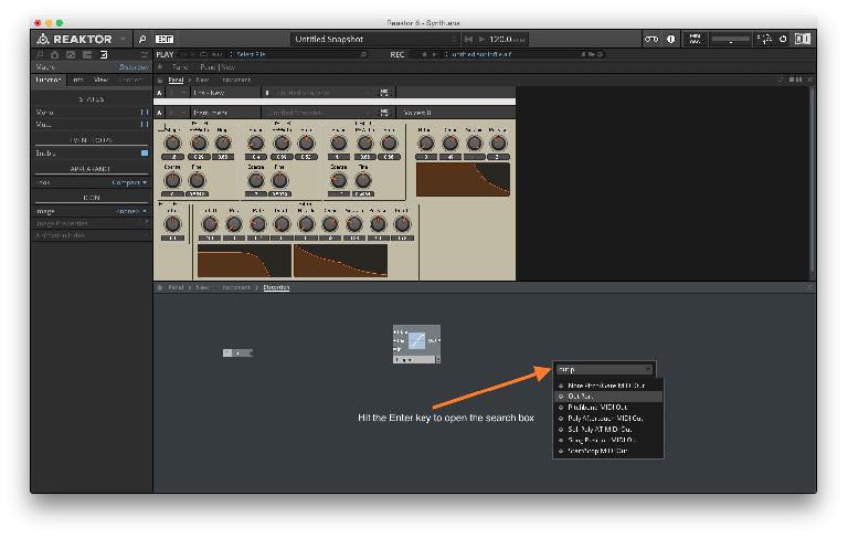
So far we have been adding modules by using the right-click menu. Another quicker way to get to the menu is to hit the Enter key in the structure view. This will open the search box where you can enter the name of a module and it will pop up in the list. Once you find the module you are looking for, just hit Enter again, or click its name from the list of modules and the module will be loaded. You will notice that even if a few letters are typed in, the list of modules that have those letters in the name will appear. This can be helpful to quickly access modules as long as you remember their names. Now use this Enter key trick to load in an In port, Out Port & the Clipper module.
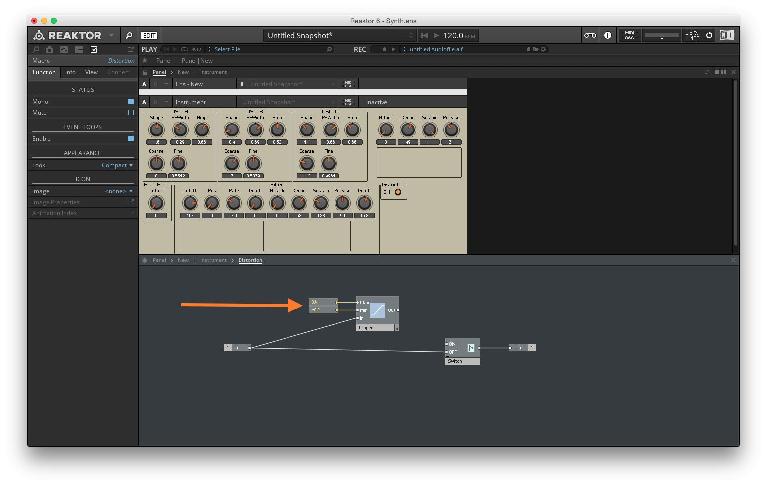
Connect the In to the In of the Clipper module and the Out of the Clipper module to the Out module.
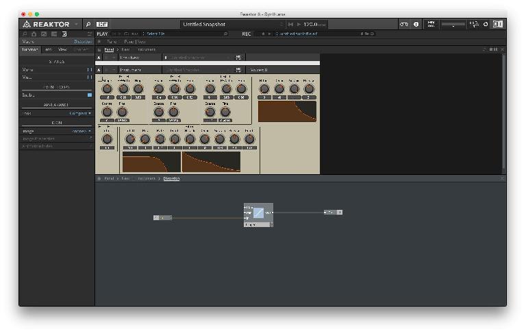
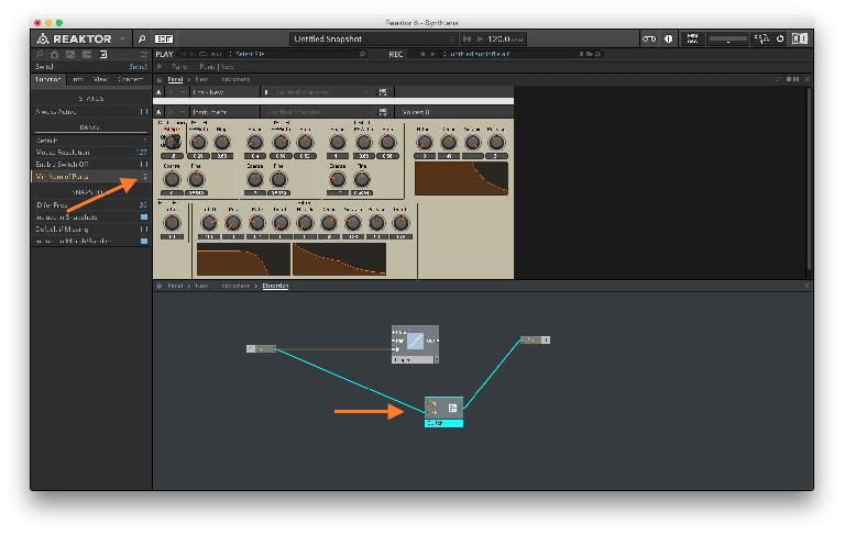
We will first create an ON/OFF switch for this distortion effect. Hit Enter and type in Switch in the search box. Load this module. Select the Switch and open the Properties tab. Under the Function tab, under Range, set the Min Num of Ports to 2. Double-click on each of these ports on the Switch and rename them to ON & OFF respectively. Connect the In port to the OFF input of the Switch (Image 53). This connection will make sure that when the distortion unit is off, the original signal passes through and we still hear sound.
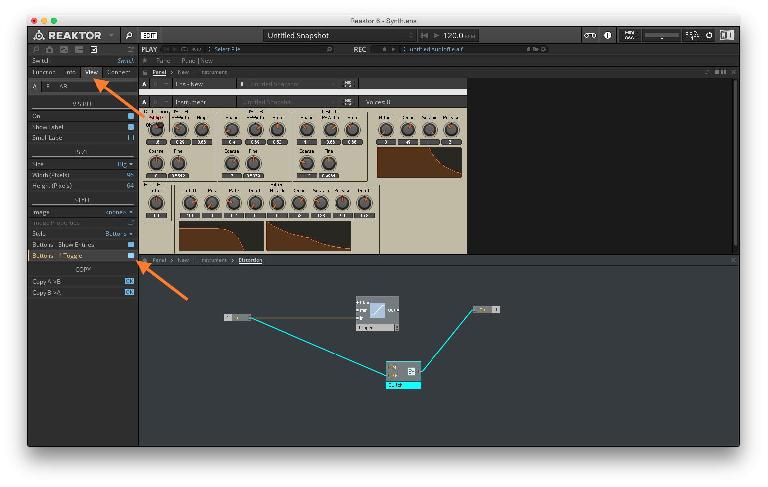
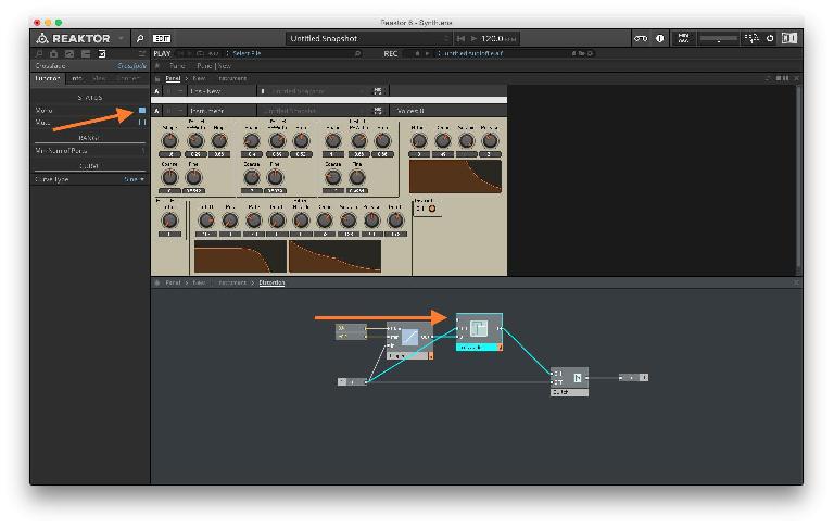
Making sure the Switch is still selected, open the View tab and under Style turn ON Buttons - 1 Toggle (Image 54). This will make sure you just have one switch on the panel rather than two switches for ON & OFF which would not be very useable.
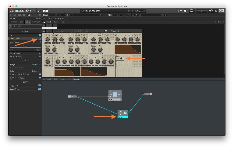
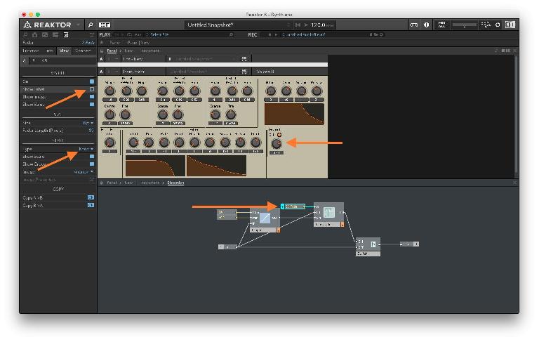
Unlock the panel view using Command-E or clicking on the lock icon. Move the Distortion macro over to the right so it does not overlap with other elements in the panel view. Lock the panel after you are satisfied with the layout. You will notice that there is the text label ‘Switch’ just above the ON switch. We do not need this label so select the Switch and open the View sub-tab of the Properties tab. Under VISIBLE, uncheck ‘Show Label’.
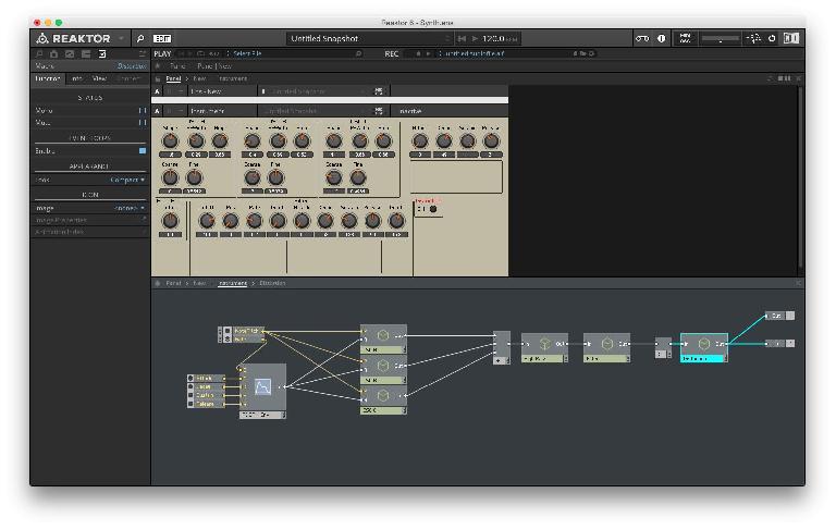
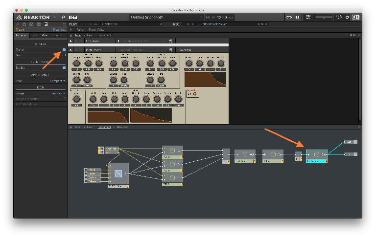
Double-click in the background of the structure view to get out of the macro. Now you will notice that the macro has an input as well as an output. We are now going to insert this macro in the synth signal but right at the end. It will be placed after the Audio Voice Combiners and before the Out. This means that the distortion is going to be applied to the entire synth signal rather than on a per voice basis. This will be much more CPU effective and sonically, practically the same.
Delete one of the Audio Voice Combiner modules. Connect the Out of the remaining Audio Voice Combiner to the In of the Distortion and the Out of the Distortion to the two Out ports.
Select the Distortion macro and in the Properties tab, under Function, make sure the Status is set to Mono. The distortion module will not work if you skip this step.
Now, while the panel view is locked, try turning ON or OFF the distortion and playing the synth simultaneously. You will notice that when the Distortion is ON, there is no sound but when its OFF you get sound. So essentially we have the bypassed signal, now we have to create the processed signal.
Double-click the Distortion module to enter its structure view. Now to distort the signal we need to set the maximum and minimum on the Clipper which acts like the threshold range for clipping. We could set dials for each of these controls but to keep things simple lets fix both to specific values. Right-click on Max and select Create Constant. Change the constant value to 0.4. Right-click on Min and select Create Constant. Change the constant value to -0.2.
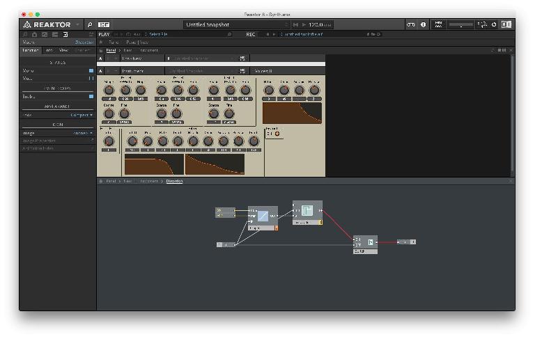
Before we connect the Clipper’s signal to the Switch we need to create a control for it so the user can dial in the amount of distortion. Hit the enter key and type in crossfade in the search box. Hit enter to load in the Crossfade module. Connect the In port to the 0 0 input of the Crossfade module, connect the Out of the Clipper to the 0 1 input of the Crossfade module and connect the Out of the Crossfade module to the ON input of the Switch.
You should notice the patch cables out of the Crossfade and Switch are red. This is because we made this macro monophonic but every new module you create, defaults to polyphonic mode (You can tell a module is in polyphonic mode when it has the two note icon as opposed to the single note icon in monophonic mode). So the Crossfade we created needs to be made mono. Select the Crossfade and in its Properties, under the Function tab, set the Status to Mono.
Now we need to create a panel control for the crossfader. Right-click the X input of the Crossfade module and select Create Control. This control defaults to a vertical fader but we can change that to a dial. Select the X-Fade control and in the Properties tab, under View, under STYLE, change the Type to Knob. In the same area under VISIBLE, turn OFF Show Label. Unlock the panel view and rearrange the knob so its not overlapping the ON switch.
Lock the panel and try out the controls of the distortion section we just created.
Delay Effect
The next effect we are going to build is a delay unit. We will insert this delay right after the distortion effect in the signal path.
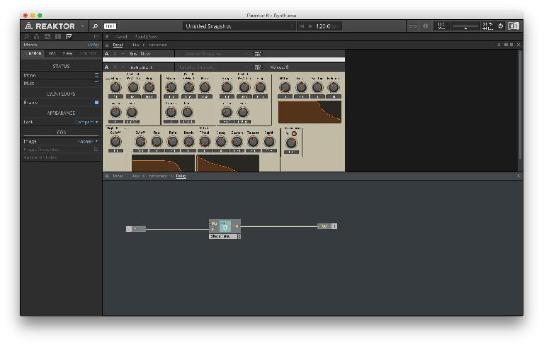
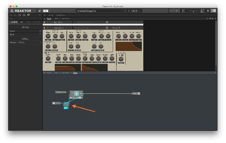
In the main structure view of the synth, right-click and select New Macro. Rename this macro to Delay (Double-click the name of the macro to rename it). Double-click the macro to enter its structure view and add the In Port, Out Port & the Single Delay module. You can hit the enter key and type in the name of the modules to load them in. Connect the In Port to the In on the Single Delay and the Out of the Single Delay to the Out Port.
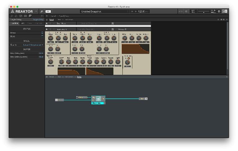
Right-click on the Dly input of the Single Delay and select Create Control. The Dly input sets the delay time. The Delay dial that is created has a range of 0ms to 1000ms which works fine for a delay time control but if you want a longer delay time, feel free to change that.
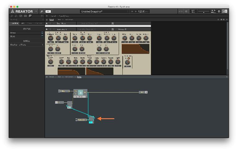
Now we need to create a feedback path so the delay repeats and sounds more natural. The way to do this is to take the output of the Single Delay and feed it back into itself. Unfortunately we can only have one signal going into one input. So if we make this connection, the previous connection of the audio coming into the delay unit will be removed. To address this we can use an Add module to mix the two signals before it goes into the Single Delay.
Hit the Enter key and type Add into the search box and load in the Add module. Connect the In Port to the first input of the Add module and the Out of the Single Delay to the second input of the Add module. Finally, connect the output of the Add module to the In of the Single Delay.
Now we have the audio signal coming into the Single Delay and the same signal mixed and fed back to the Single Delay. Unfortunately we don’t have a way to control this feedback. The entire signal is being fed back into the delay. If we were to multiply the feedback signal with a dial that was outputting values of a range from 0 to 1, we will then be able to control that feedback amount with the dial. Let's set this up.
Hit the Enter key and enter Multiply in the search box. Load in the Multiply module. Disconnect the Single Delay output that’s going to the Add module and connect it to the top input of the Multiply module. Right-click the bottom input of the Multiply module and select Create Control. This new dial named Mult has a range of 0 to 1 which is exactly what we need. Double-click on its name and rename it to Feedback. Finally, connect the output of the Multiply to the second input of the Add module.
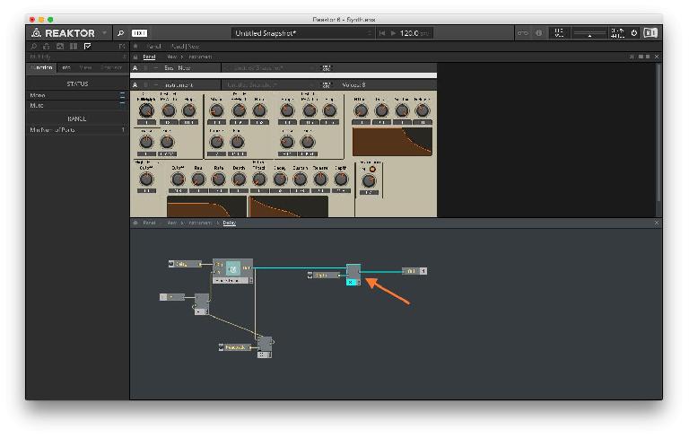
It would be nice to have a depth control for this effect. The best way to do this is to multiply the signal coming from the delay with a dial that is outputting a range from 0 to 1. Just like we did for the feedback control.
Disconnect the output from the Single Delay that is going to the Out module. Hit the enter key and type in Multiply in the search box and load in the Multiply module. Connect the output of the Single Delay module to the top input of the Multiple module. Right-click on the second input of the Multiply module and select Create Control. Rename this newly created dial to Depth.
This completes the structure of the delay unit but the panel view is a mess. Unlock the panel using Command-E and move the Delay macro below to the Distortion macro. Make sure the 3 dials in the Delay module are not overlapping. Lock the Panel by once again hitting Command-E.
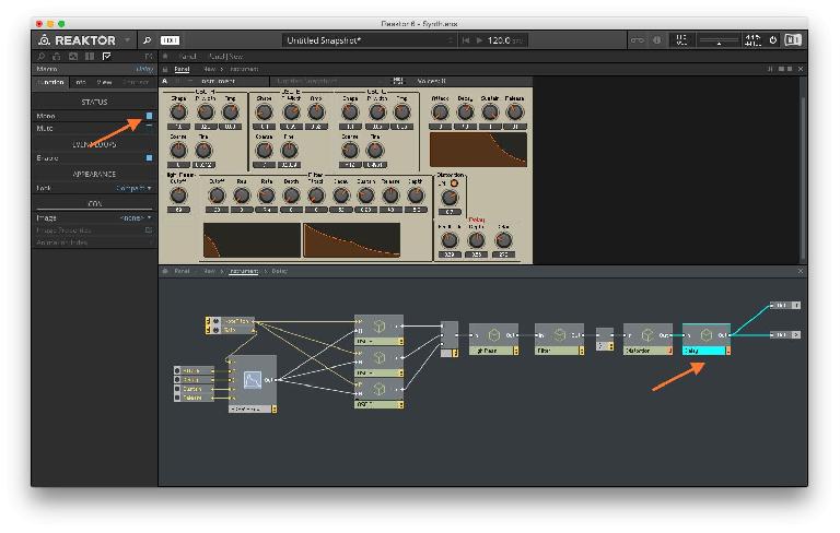
We have created the delay unit but it's not yet connected to the synth engine. Double-click in the background of the structure view to get out of the Delay macro. Here, connect the output of the Distortion macro to the input of the Delay macro and the output of the Delay macro the two Out Ports. The patch cables out of the delay are red right now because the macro is polyphonic. Select the Delay macro and in the Properties tab, under Function, set the STATUS to Mono by checking the option.
Try out the delay parameters. Again, if anything is not working as expected, check the connections and review the instructions outlined in this section.


 © 2024 Ask.Audio
A NonLinear Educating Company
Discussion
Want to join the discussion?
Create an account or login to get started!