The Filter Section
The next obvious step in our synth-building exercise is to create the filter section. We will create a filter section that has a low pass filter with cutoff frequency & resonance controls. We will also create a very basic high pass filter that will filter the signal going into the low pass. Very similar to the Roland Juno 60 & Juno 106. We will also create modulation options for the cutoff frequency using a filter envelope and an LFO.
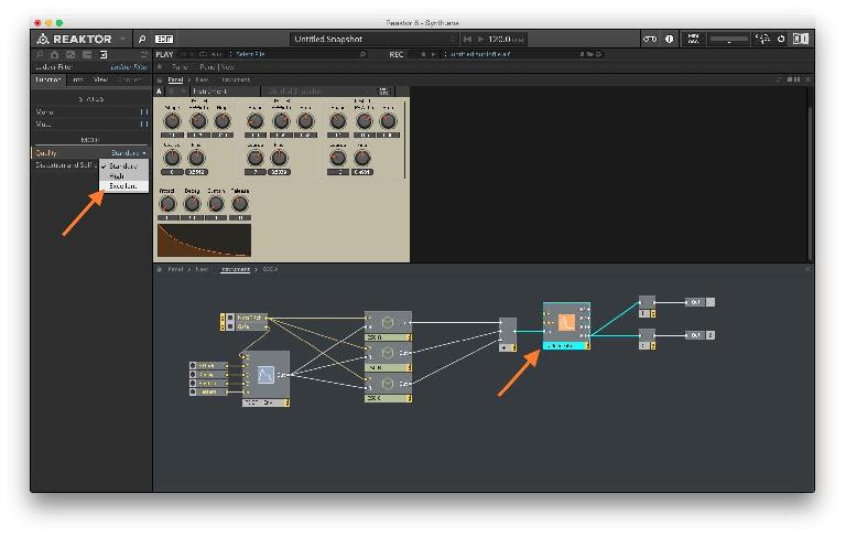
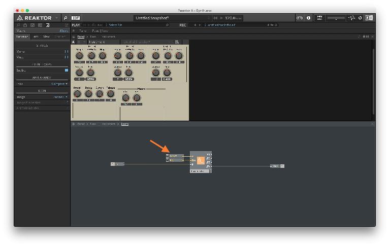
Make sure you’re on the Instrument page, then Right-Click in the background of the structure view and select Built-In Module > Filter > Ladder. This will load in the low pass Ladder filter.
Connect the output from the Add module to the In of the Ladder Filter. Connect the LP4 out from the Ladder Filter to the inputs of the two Audio Voice Combiner modules.
The LP4 out will have a 24 dB/oct slope, which is the most common filter steepness so we will stick with that.
You will notice that I also switched the quality to Excellent (Function > Mode > Quality). This will take up a little bit more CPU but will give you a better output quality. If the CPU usage is too high for your computer, switch back to standard.
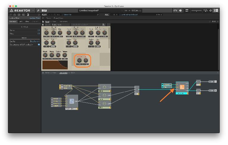
Right-click on the P & Res input of the Ladder Filter and select Create Control for each. Unlock the panel view by hitting Command-E or click the lock icon. Move the two new controls to an empty area of the panel view. Lock the panel and try out the controls. You should be able to work the filter with its two controls.
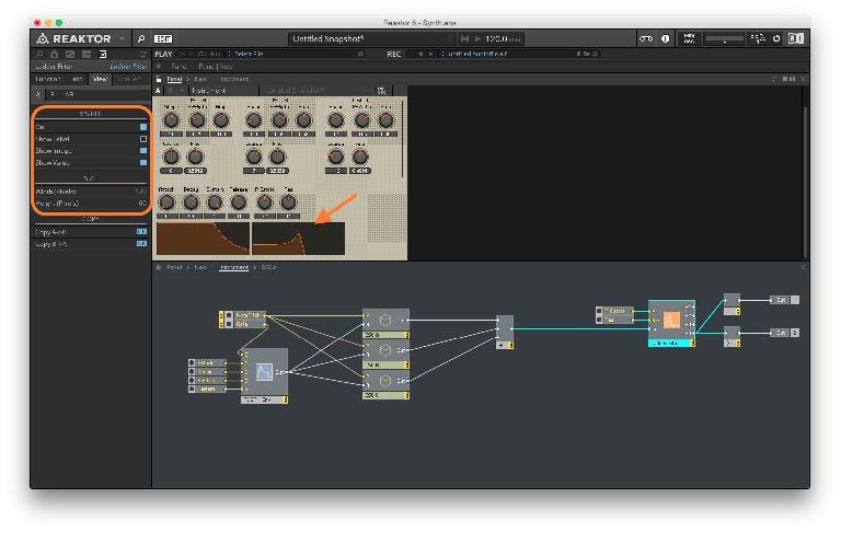
Just like the ADSR Envelope, the Ladder Filter also has a view option with a graph that shows how the filter is working. Select the Ladder Filter and under the Properties tab, under View, turn ON VISIBLE. You can disable Show Label and resize the graph with the SIZE controls. I tried to match it to the ADSR graph size.
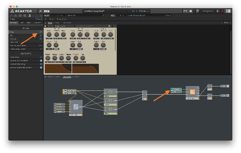
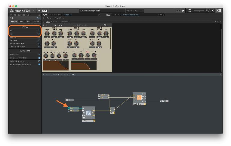
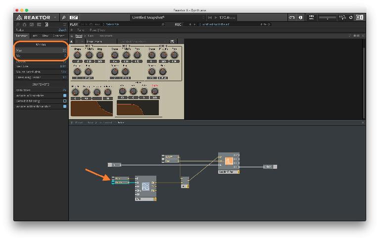
Now when you work the controls of the filter, the graph updates in real time showing you the effect of moving the cutoff frequency as well as the resonance. It’s also a great way to understand how filtering works in general. One thing you may not notice is that the P Cutoff control range is not quite ideal. By default it’s in the range of 20–120. Think of this as MIDI note numbers. 20 would be a very low note so we don’t really need to go any lower but 120 is not quite the highest note. Even though we will never play note number 120, harmonics of lower notes may reach up to that value. So let’s change that to the maximum 127. Select P Cutoff and in the Properties tab, under Function set the Max to 127.
Now before things get messy, let’s create a macro just for the filter section. We will eventually be adding in an LFO and an envelope so it’s best to keep things tidy by placing everything inside a macro.
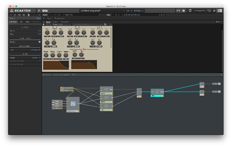
Right-click in the background of the structure view and select New Macro. Select the P Cutoff, Res dials and the Ladder Filter module and hit Command-X to cut them. Double-click on the new Macro to enter its structure view and hit Command-V to paste the objects. Also create one In and Out ports each. You will find these in the Terminal section of the Built-in Module Right-click menu. Connect the In to the In of the Ladder Filter & the LP4 output of the Ladder Filter to the Out port.
At this point it would good to rename the P Cutoff dial to Cutoff. Most synthesizers just use the term cutoff so there is no need to have the P in front of that.
Double-click in the background of the structure view to go back out of the macro. Connect the output of the Add module to the input of the macro and the output of the macro to the inputs of the two Audio Voice Combiner modules. Double-click on the name of the macro and rename it to Filter. Move the user interface elements around so it looks neat and clean.
Play the synth again to check if everything is still working. We haven’t changed the functionality of the synth, just rearranged things in the UI and moved modules into macros to make things neater.
Filter Cutoff Modulation with LFO
Let’s now create the LFO that will modulate the cutoff parameter of the Ladder Filter.
Double-click the Filter macro to enter its structure view. Right-click in the background of the structure view and select Built-In Module > LFO, Envelope > LFO. Right-click on the F & A inputs of the LFO and select Create Control.
The panel view is messed up again so unlock the panel by hitting Command-E and rearrange the newly created knobs. For now we need to connect the LFO’s Sin output to the Filter’s P input. But we already have the Cutoff dial connect to the P. We don’t want to lose that control so we will use an Add module to combine both the signals.
Right-click in the background of the structure view and select Built-In Module > Math > Add. Connect the Sin output to one of the inputs of the Add and the Cutoff dial’s output to the other input.
Now the Freq dial for the LFO controls the rate of modulation. The default range for this control is not ideal. Select the Freq dial and in the Properties tab, under Function, Set the Min to 0.1 and Maximum to 25. Now the LFO has a nice wide range. Double-click the Freq dial in the structure view and rename it to Rate.
Try playing the synth and change the Freq dial values. You should hear the modulation, but you will also notice that the depth of modulation is very low. Even with the Ampl dial set at maximum the modulation sounds very subtle. This is because the range of the LFO modulation as defined by its amplitude is very low. At the maximum of 1 the LFO modulates the frequency by just a few hertz. We need to increase that range to make it more significant.
Select the Ampl dial and in the Properties tab, under Function, Set the Min to 0 and Maximum to 20. Double-click the Ampl dial in the structure view and rename it to Depth. (setting the minimum value to 0 will ensure the LFO modulation is completely OFF when the dial is at its lowest value)
Now play around with the LFO controls as well as the filter controls to see how well the controls work. Feel free to change the minimum and maximum values for any of the controls to your personal taste.
Filter Cutoff Modulation with Envelope
Now that we have the LFO modulation working great, let's create the filter envelope.
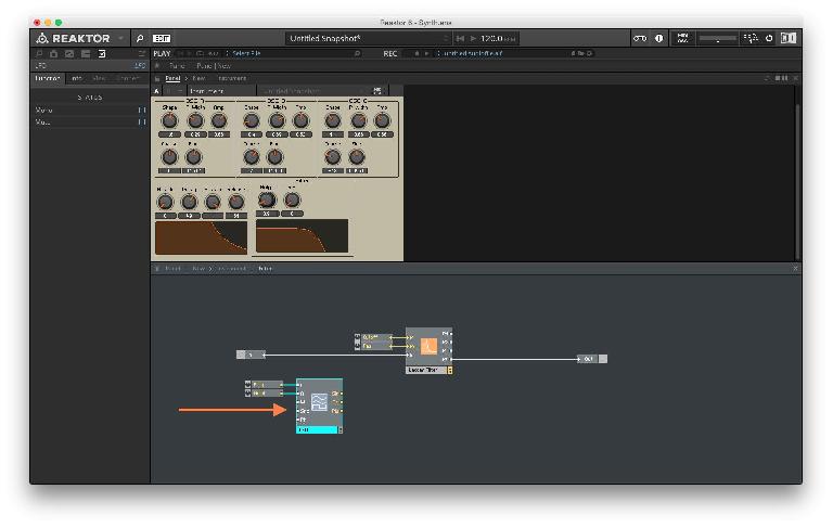
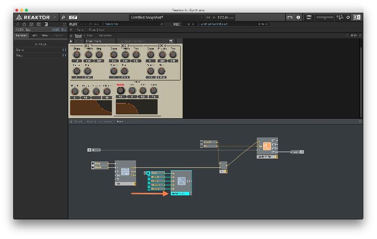
Make sure you’re still inside the Filter macro structure view. Right-click in the background of the structure view and select Built-In Module > LFO, Envelope > ADSR. Right-click on each of the A, D, S & R inputs and select Create Control. For the G input we don’t want a control but a MIDI trigger so right-click on the structure background and select Built-In Module > MIDI In > Gate and connect that to the G input of the ADSR.
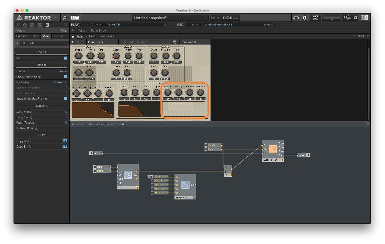
The panel view is a mess again. Unlock the panel by tapping Command-E and move the ADSR controls to the right. You can choose to enable the graph view for this envelope just like we did for the amplitude envelope, but you will notice that the graph is empty. Empty graphs indicate that the connections have not been made for the module.
We now need to connect the signal from the envelope to the filter cutoff input. Just like we combined the dial that controls the filter cutoff with the LFO signal, we now need to bring in this envelope signal and have all 3 signals going into the filter’s cutoff input.
Select the Add module and in its Properties tab, under Function set the Min Num of Ports to 3.
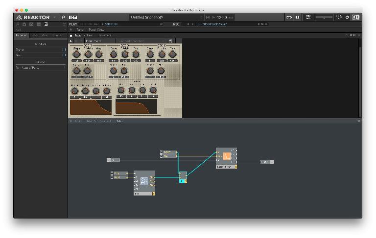
Now if you try to connect the ADSR out to the 3rd input of the Add module, Reaktor won’t let you do so. The reason for this is that you can’t connect an audio rate signal to a control rate input (Audio rate is indicated by the white color cables and inputs and control rate is indicated by yellow cables and inputs) .
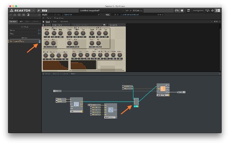
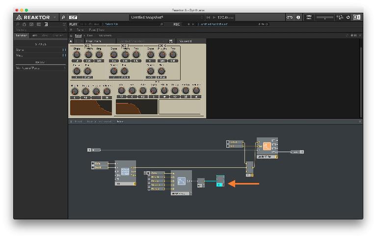
Right-click in the background of the structure view and select Built-In Module > Auxiliary > A to E. This module will convert the audio rate signal to control rate. Connect the ADSR out to the in of the A/E module. Now before we connect this to the Add module we need to create a way to control the depth of this envelope modulation. Right-click and select Built-In Module > Math >
Multiply. Connect the out of the A/E module to one of the inputs of the Multiply module.
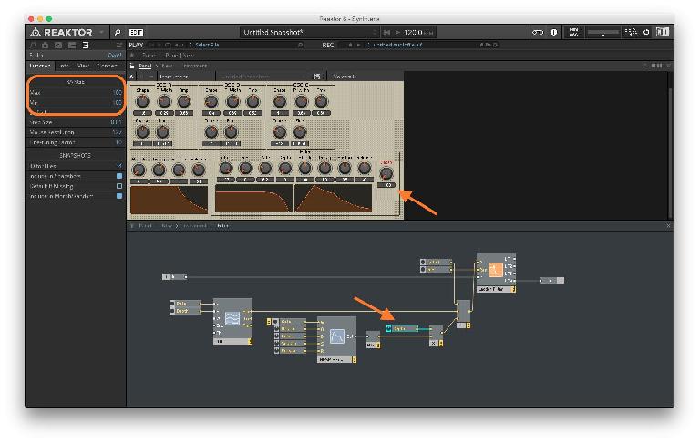
We now need a dial to control the depth of the filter envelope signal. This dial should have a range of -100 to 100. At 0 the filter envelope is completely OFF, at 100 it’s at high modulation depth and at -100 it’s at high modulation depth with an inverted shape.
Right-click on the empty input of the Multiply module and select Create Control. Connect the output of the Multiply module to the input of the Add module. Select the newly created Mult dial and set its range to -100 to 100. Double-click on the dial to rename it to Depth. Unlock the panel and move the Depth dial to the right.
Now try playing with the controls of the envelope and listen to the filter cutoff modulation. You should be able to have the LFO and the envelope work simultaneously. This kind of a setup can lead to some pretty interesting modulation possibilities.


 © 2024 Ask.Audio
A NonLinear Educating Company
Discussion
Want to join the discussion?
Create an account or login to get started!